
Microfluidic test systems with gas bubble reduction

a microfluidic test and gas bubble reduction technology, applied in the direction of fluid analysis using sonic/ultrasonic/infrasonic waves, instruments, etc., can solve the problems of affecting the testing to be performed on liquids, affecting the overall time required for a particular test regime, and the technology associated with microfluidic testing remains problematic, so as to reduce or prevent the presence of gas bubbles in liquids, the effect of reducing or preventing the presence of gas

Inactive Publication Date: 2008-02-28
HEWLETT PACKARD DEV CO LP
View PDF1 Cites 6 Cited by
  • Summary
  • Abstract
  • Description
  • Claims
  • Application Information

AI Technical Summary

Benefits of technology

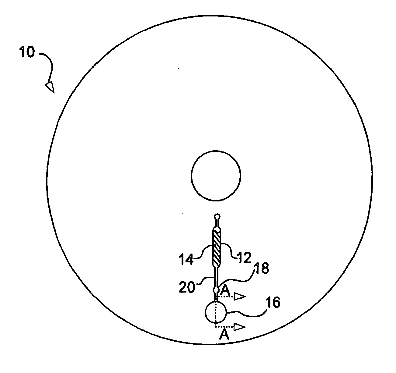
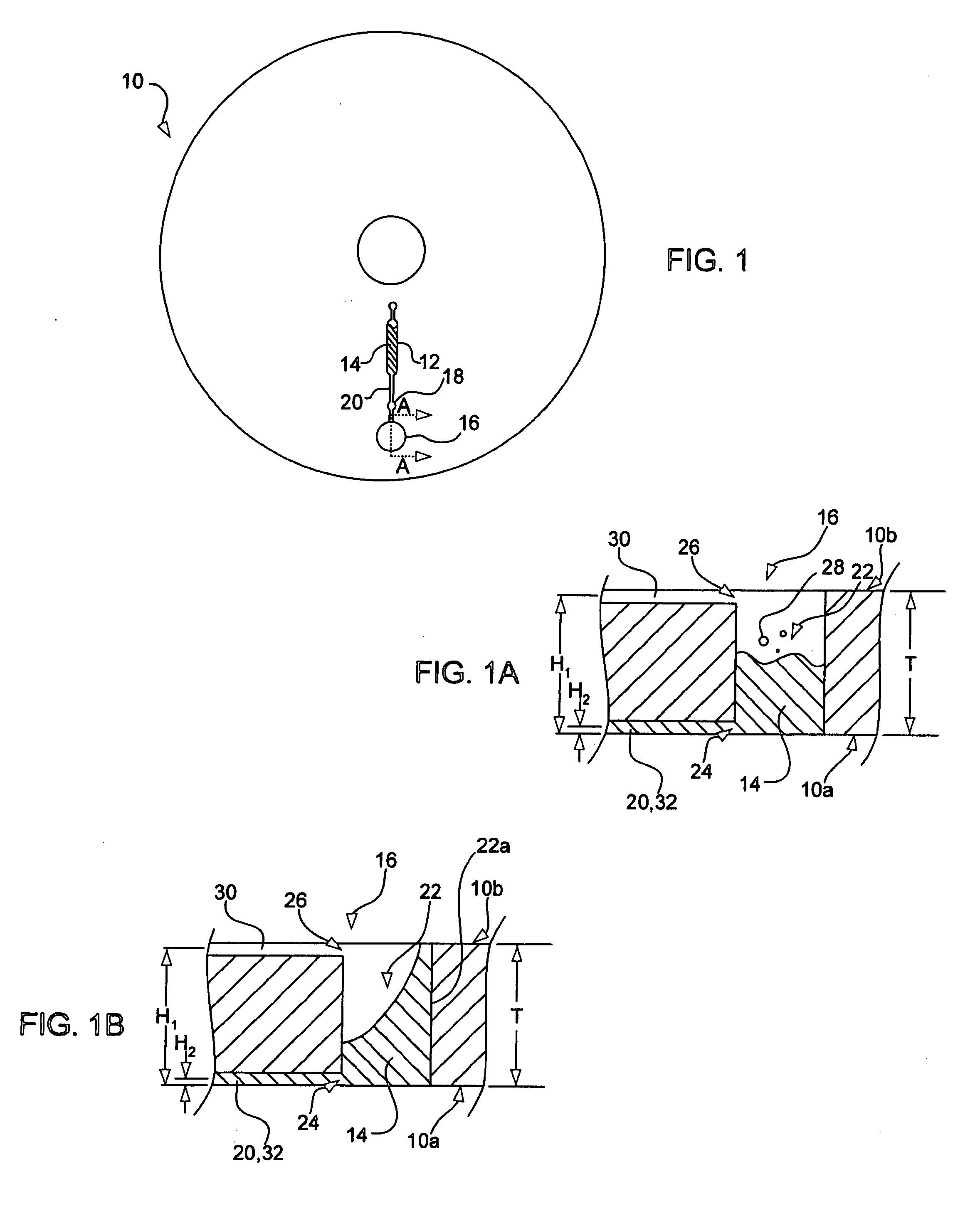
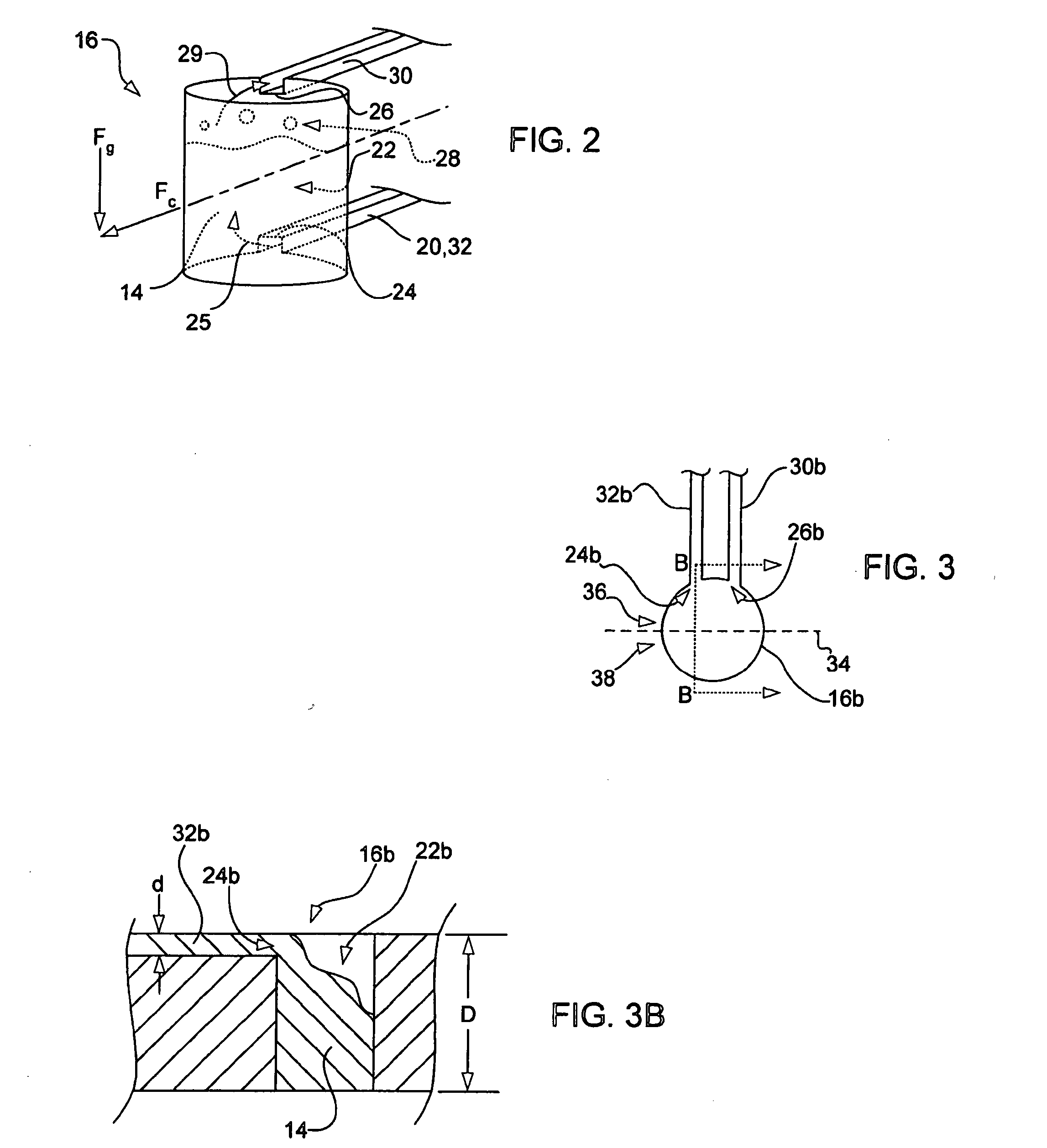
The present invention provides a system for manipulating liquids on a microfluidic level while reducing or preventing the presence of gas bubbles. The system includes a reservoir for testing liquids, with a testing chamber that can receive the liquid and a gas outlet to expel gas. The gas outlet has a higher elevation than the liquid inlet, so as the testing chamber rotates, the gas is expelled through the gas outlet, reducing or preventing gas bubble presence in the liquid. The invention also includes a method for reducing or preventing gas bubble presence in a microfluidic liquid to be tested.

Problems solved by technology

In addition, the response time of reactions is often much faster in microfluidic systems, leading to a decrease in the overall time required for a particular test regime.
While microfluidic testing is increasing in popularity, the technology associated with microfluidic testing remains problematic in a number of areas.
In particular, it has been found that as liquids are centripetally manipulated through various microchannels and chambers formed on or in microfluidic test coupons, gas bubbles can be formed or entrained in the liquids and can interfere with the testing to be performed on the liquids.
For example, when liquid is delivered to an optical test chamber to be optically analyzed, the presence of gas bubbles within the liquid can adversely affect the accuracy of the optical test.
Accordingly, while it is desired to use microfluidic test systems in a wide range of applications, the limitations presented by the presence of gas bubbles in microfluidic manipulation of fluids remain problematic.

Method used


Image

  • Microfluidic test systems with gas bubble reduction
  • Microfluidic test systems with gas bubble reduction
  • Microfluidic test systems with gas bubble reduction

Examples


Embodiment Construction

)

[0016] Before particular embodiments of the present invention are disclosed and described, it is to be understood that this invention is not limited to the particular process and materials disclosed herein as such may vary to some degree. It is also to be understood that the terminology used herein is used for the purpose of describing particular embodiments only and is not intended to be limiting, as the scope of the present invention will be defined only by the appended claims and equivalents thereof.

[0017] In describing and claiming the present invention, the following terminology will be used:

[0018] The singular forms “a,”“an,” and “the” include plural referents unless the context clearly dictates otherwise.

[0019] As used herein, the terms “test coupon” or “coupon” are to be understood to refer to a device used to test one or more microfluids in a centrifugation test regime. Test coupons utilized in the present invention can include, but are not limited to, disk-shaped devic...


PUM

PropertyMeasurementUnit
thicknessaaaaaaaaaa
thicknessaaaaaaaaaa
thicknessaaaaaaaaaa

Abstract

A reservoir for use in testing a liquid as part of a microfluidic testing system, includes a testing chamber configured to receive the liquid to be tested. A liquid inlet is fluidly coupled to the testing chamber to allow ingress of the liquid into the testing chamber. A gas outlet is fluidly coupled to the testing chamber to allow egress of gas out of the testing chamber. The gas outlet has an elevation that is higher than an elevation of the liquid inlet such that, as the testing chamber is rotated, the gas is expelled out of the testing chamber through the gas outlet, thereby reducing or preventing a presence of gas bubbles in the liquid.

Description

CROSS-REFERENCE TO RELATED APPLICATION [0001] This is a divisional of copending application Ser. No. 11 / 168,775, filed on Jun. 28, 2005, which is hereby incorporated by reference.FIELD OF THE INVENTION [0002] The present invention relates generally to systems for manipulating microfluids while minimizing the presence of gas bubbles therein. BACKGROUND OF THE INVENTION [0003] The use of microfluidic systems for the acquisition of chemical and biological information is becoming increasingly popular due to a number of considerations. For example, complicated biochemical reactions, when conducted in microfluidic volumes, may be carried out using very small volumes of liquid. As the volume of a particular liquid needed for such testing regimes is small, often on the order of nanoliters, the amounts of reagents and analytes used can be greatly reduced. Reduction in the amounts of reagents and analytes can greatly reduce the costs associated with microfluidic testing compared to convention...

Claims


Application Information

Patent Timeline
Patent Type & Authority Applications(United States)
IPC IPC(8): G01N29/02
CPCG01N35/00069Y10T436/111666G01N2021/054
Inventor HARDING, PHILIPBEATTY, CHRISTOPHER C.
Owner HEWLETT PACKARD DEV CO LP
Learn More