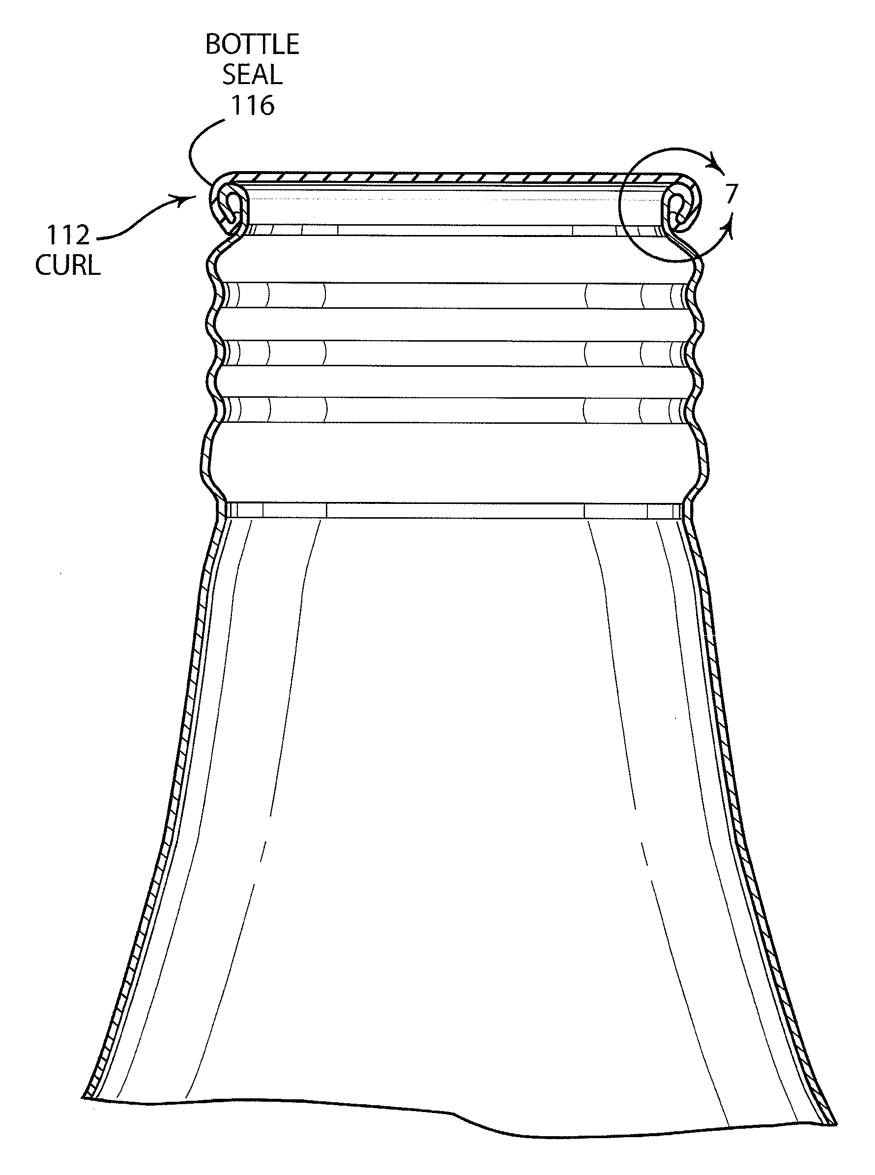
Metal bottle seal

a technology of metal bottles and seals, applied in the direction of caps, liquid handling, transportation and packaging, etc., can solve the problems of great difficulty encountered

Inactive Publication Date: 2008-02-28
STOLLE MACHINERY +1
View PDF86 Cites 51 Cited by
  • Summary
  • Abstract
  • Description
  • Claims
  • Application Information

AI Technical Summary

Problems solved by technology

There has been a great deal of difficulty encountered in providing a twist-off cap that is capable of providing a suitable and reliable se

Method used


Image

  • Metal bottle seal
  • Metal bottle seal
  • Metal bottle seal

Examples


Embodiment Construction

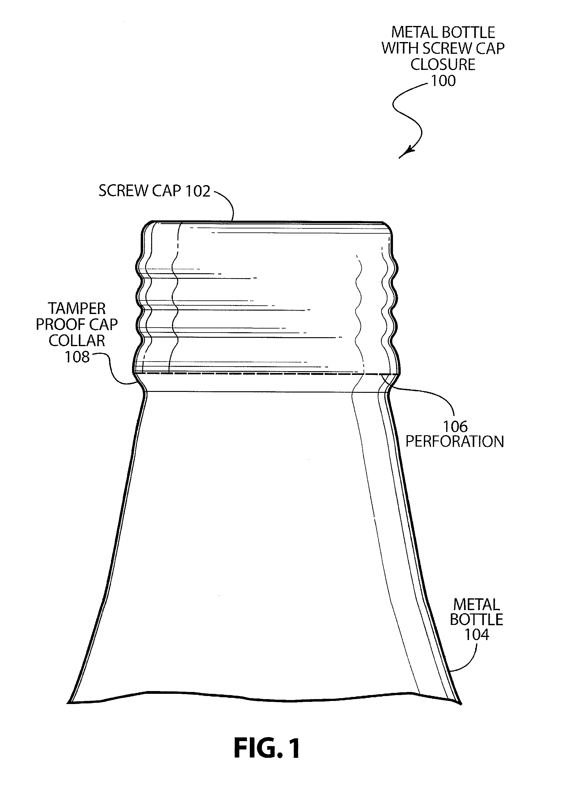
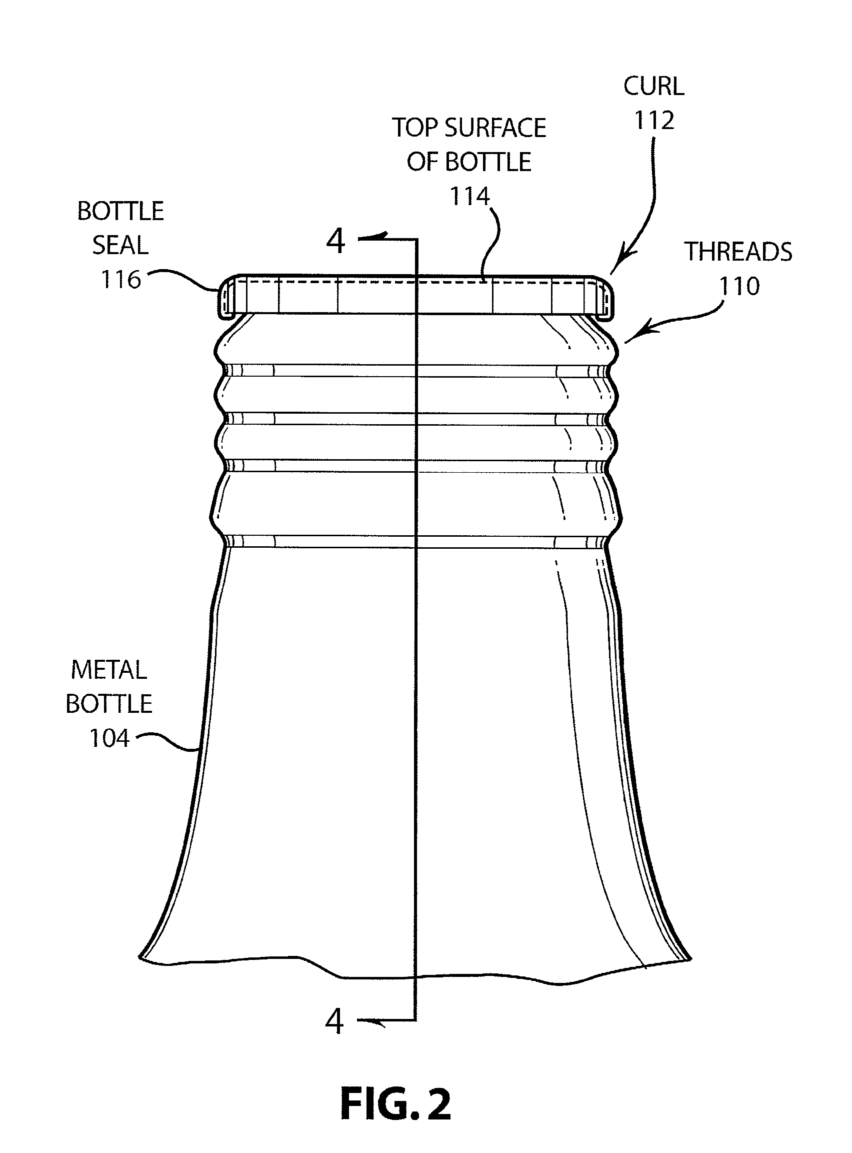
[0023]FIG. 1 is a schematic side view of a metal bottle having a closure such as a screw cap that incorporates the seal (not shown) of the present invention. As shown in FIG. 1, a screw cap 102, including a tamperproof cap collar 108 (roll on closure or pilfer-proof closure), is rolled onto and formed to the threads of metal bottle 104. In accordance with this process, a straight sidewall cap is slipped over the metal bottle 104. Screw threads are pre-formed in the metal bottle 104. A downward pressure is then placed on the top of the screw cap 102 which is sufficient to create pressure on the seal between the screw cap 102 and metal bottle 104. In conventional screw cap metal bottles, pressures of approximately 300 pounds per square inch are required to form an adequate seal.

[0024] In order to seal the cap, a roller then rotates around the outer surface of the metal screw cap 102 to force the straight sidewalls of the metal screw cap 102 to conform with the threads of the metal bo...


PUM


Abstract

Disclosed is a metal bottle seal that is disposed on the curl of the metal bottle. The bottle seal may be held in place by crimping of the curl. In addition, adhesive may be used to hold the bottle seal on the curl. Adhesives can be used that fill discontinuities that may exist in the curl as a result of substantial drawing and ironing of the metal. Further, the metal bottle seal can be made of a material or laminated with a material that is soft enough to fill the discontinuities. The seal can be preformed as a continuous annulus for easy application to the top of the metal bottle. The metal bottle seal can also be used in conjunction with a cap seal to ensure an adequate and reliable seal.

Description

CROSS REFERENCE TO RELATED APPLICATION [0001] This application is based upon and claims the benefit of U.S. provisional application No. 60 / 823,122, entitled “METAL BOTTLE SEAL,” filed Aug. 22, 2006, the entire disclosure of which is herein specifically incorporated by reference for all that it discloses and teaches.BACKGROUND OF THE INVENTION [0002] There has been a great deal of interest in developing technology to support the introduction of metal containers, formed in such a way to allow the shape and finish to accept a bottle closure such as a crown cap or a roll-on / twist-off cap. Such containers are commonly known as metal bottles. There has been a great deal of difficulty encountered in providing a twist-off cap that is capable of providing a suitable and reliable seal that provides a high degree of integrity, and in the case of a screw-on cap, will allow the user to adequately reseal the metal bottle. SUMMARY OF THE INVENTION [0003] An embodiment of the present invention may ...

Claims


Application Information

Patent Timeline
IPC IPC(8): B65D1/02B65B7/28
CPCB65D1/0238B65D41/12B65D2251/0093B65D2251/0015B65D51/20B65D1/0207B65D39/08B65D1/0246B65D41/125
Inventor OLSON, CHRISTOPHERGILLEST, EDMUND
Owner STOLLE MACHINERY
Why Eureka
Try Eureka