

LED lantern assembly
a technology of led lanterns and assembly parts, which is applied in the field of light sources, can solve the problems of insufficient lumens or candlepower to meet the 3-4 mile visibility requirement, high danage risk, and insufficient lumens or candlepower
- Summary
- Abstract
- Description
- Claims
- Application Information
AI Technical Summary
Problems solved by technology
Method used
Image

Examples
first embodiment
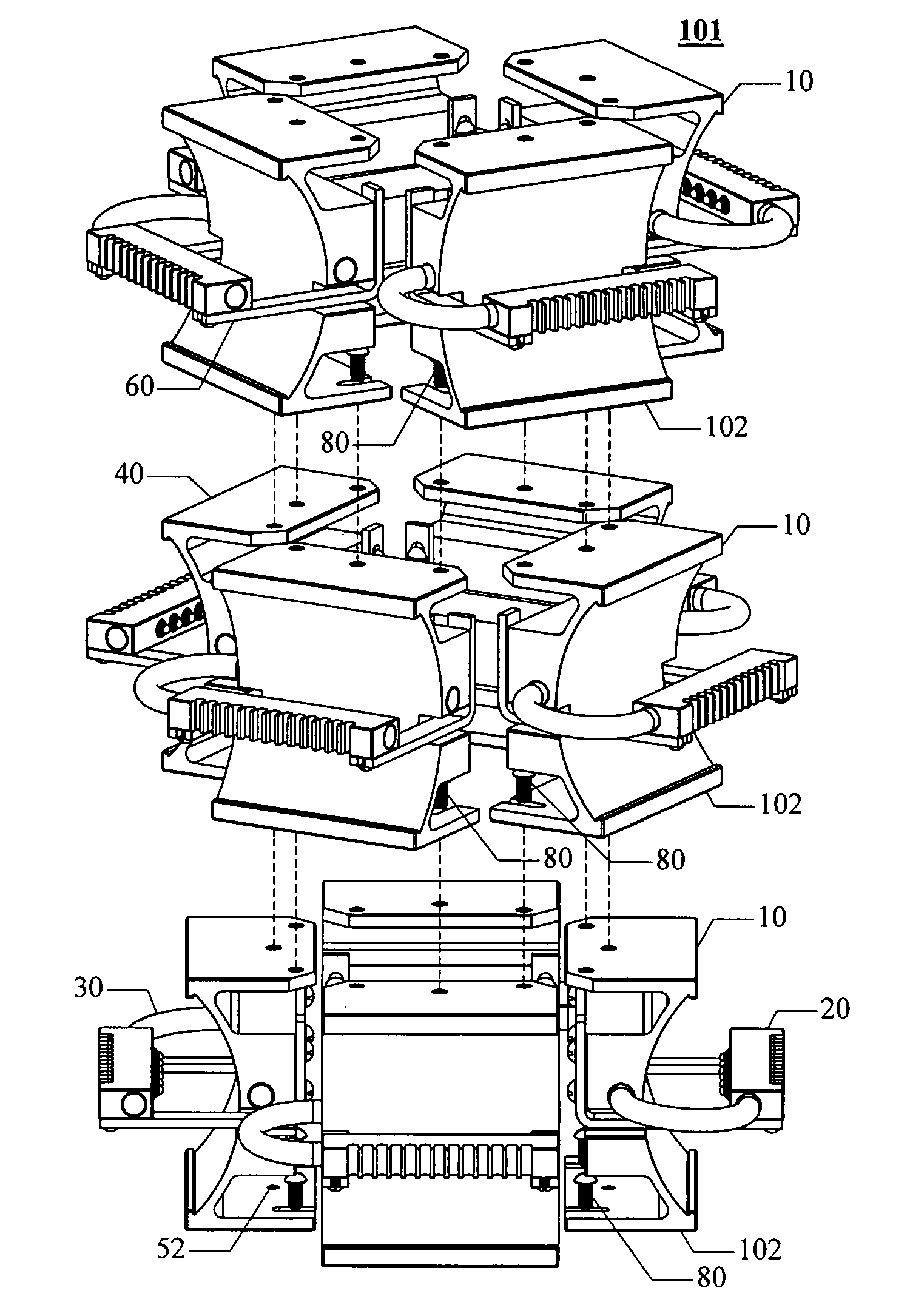
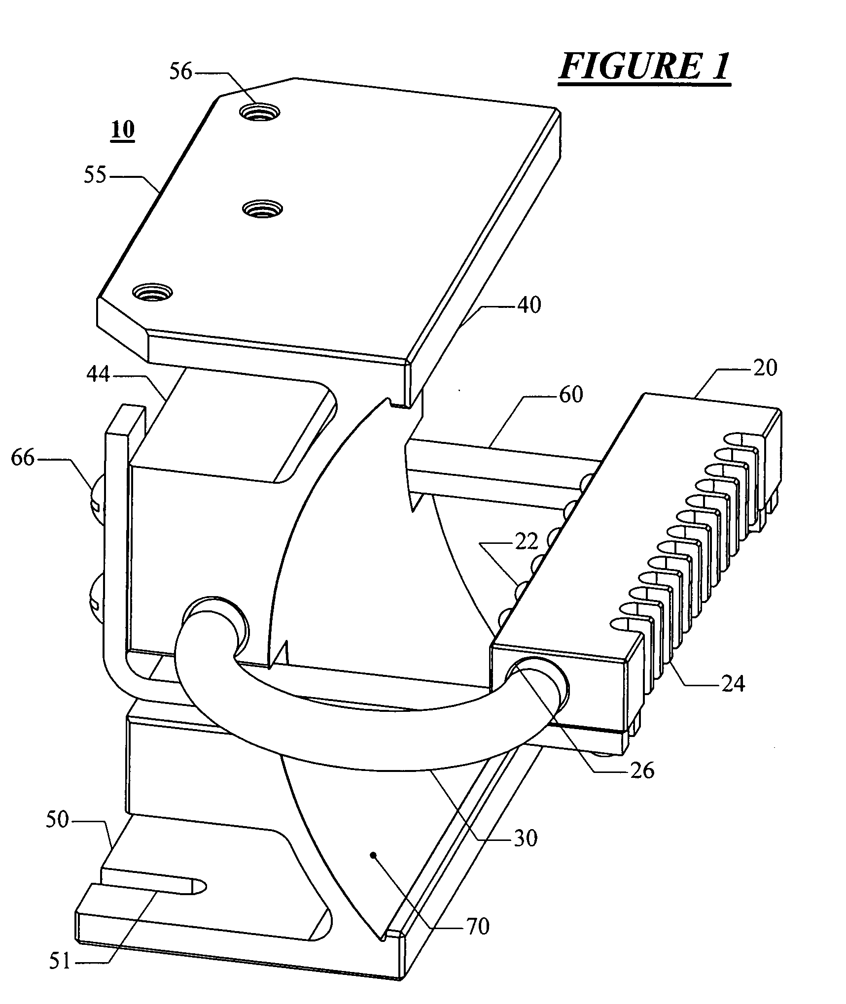
[0046]Referring to FIGS. 1 and 2, the light emitter assembly 10 is shown in both assembled and exploded views. The primary components of the light emiter assembly are the LED mounting block 20 with its LEDs 22, the heat pipe 30, the reflector mounting block 40 with its mirror 70, and a bracket 60 for connecting the LED mounting block 20 to the reflector mounting block. In these drawings, the wiring which connects the LEDs 22 to a power supply and a power supply are not shown for clarity. However, as generally understood by those skilled in the art, a wire pair connects to each LED 22 and is run on the surface of the LED mounting block 20 and then down a horizontal arm 61 of the bracket 60 and thence to a standard DC power supply.
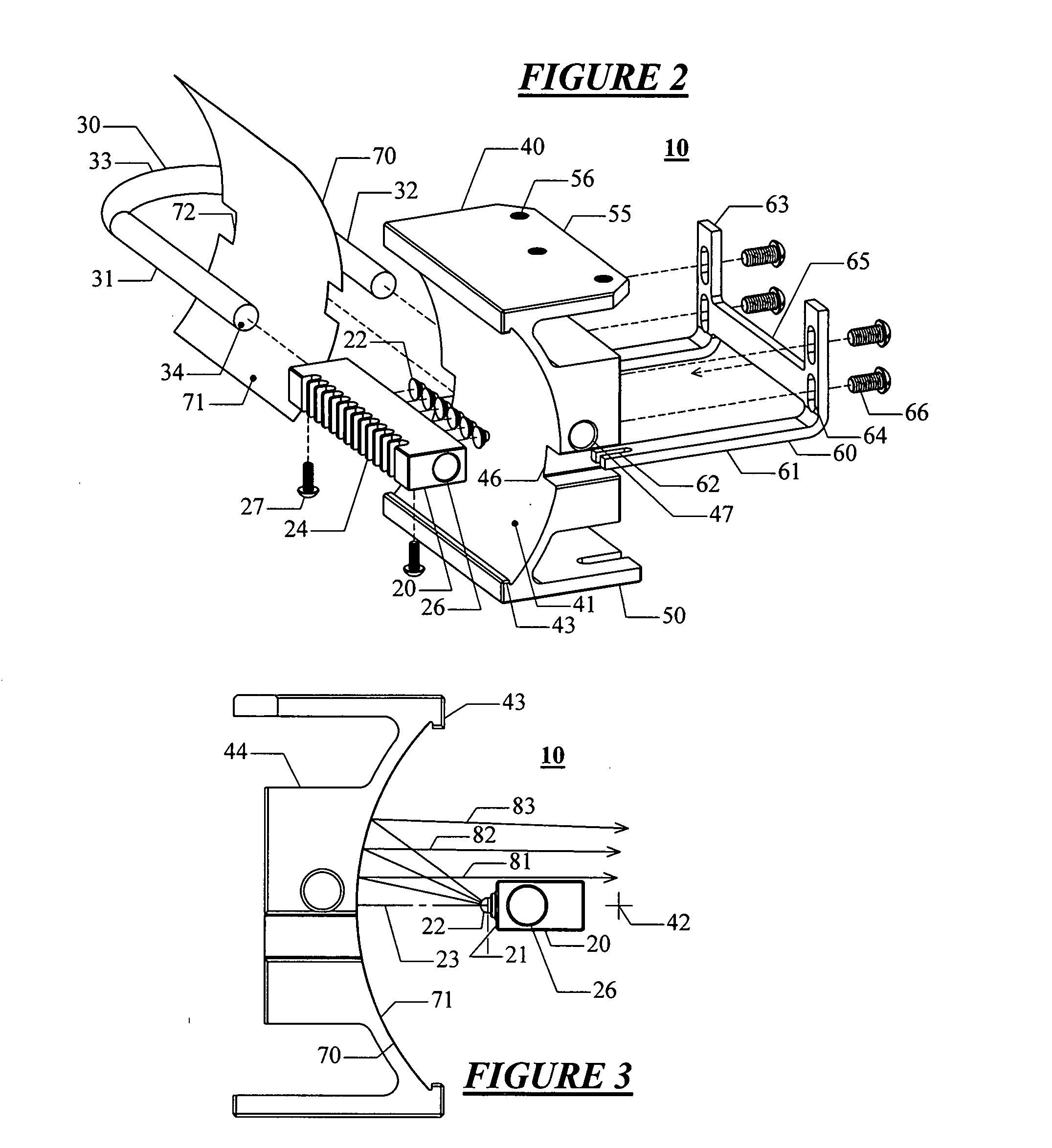
[0047]The LED mounting block 20 is an rectangular prismatic aluminum alloy bar having a regular array of LEDs mounted on a first horizontally extending long vertical LED mounting face 21. On the side of the mounting block 20 opposed to the LED mounting face ...
second embodiment
[0074]In order to effectively utilize the heat rejection capabilities of the secondary heat pipes 230, they must convey the heat to a location external to the lens unit 370 of the lantern 300. This is accomplished by inserting the heat rejection ends 232 of the heat pipes 230 into a radiator that rejects heat to the exterior of the lantern.
[0075]Radiator 380, one embodiment of such a radiator, has a vertical axis of symmetry and consists of, starting at its lower end, a centralizing boss 381, a vertically extending cylindrical core having multiple external horizontal cooling fins 383, and a conical cap with an upwardly extending projection or bird spike 384. The centralizing boss 381 is a short right circular cylindrical disk of smaller diameter than the fins of the radiator. The centralizing boss 381 is attached to the downwardly facing lower side of the first fin 383. An annular flat sealing gasket 374 is fitted to the lower side of the first fin 383 and is coaxially placed around...
third embodiment
[0080]Referring to FIG. 15, a light emitter assembly 410 is shown in a side profile view. The heat pipe and mounting hardware are removed so that the light ray paths can be shown clearly. Light emitter assembly 410 is substantially similar to light emitter assembly 10, but with the difference that the reflector arcuate cylindrical face 441 of the reflector mounting block 440 has a parabolic cross-section. In all other respects, the features of the components of the light emitter assembly 410 are the same as those for light emitter assembly 10.
[0081]For light emitter assembly 410, the LEDs 22 are positioned so that their centers lie on the focal point of the parabola of the reflector mounting block 440. Light emitted from the LEDs 22 is reflected from the mirror 70 which closely conforms to the substantially parabolic face of the reflector mounting block 440 and which is retained by the retainer lips 43. The properties of a parabolic reflector are such that light emitted at the focal...
PUM
 Abstract
Description
Claims
Application Information