Cover release mechanism for a dispenser

a dispenser and release mechanism technology, applied in the field of dispensers, can solve the problems of unable to incorporate configuration into hands-free dispensers and problematic latching mechanisms

Active Publication Date: 2008-03-06
KANFER JOSEPH S
View PDF9 Cites 3 Cited by
  • Summary
  • Abstract
  • Description
  • Claims
  • Application Information

AI Technical Summary

Benefits of technology

[0005]It is an object of this invention to provide a wall-mounted dispenser having features not provided in the prior art for opening the dispenser. Although this invention is particularly useful in wall-mounted hands-free type dispensers, the practice of this invention is not limited thereto.
[0006]In general, this invention provides a wall-mounted dispenser that includes a backplate mounted to affix the dispenser to a wall structure. The backplate has a catch proximate a top of the backplate. A cover is pivotally secured to the backplate proximate a bottom of the backplate to move between an open position, at which the dispenser may be refilled, and a closed position, at which the dispenser may be actuated. The cover includes a latch that engages the catch associated with the backplate, this engagement serving to retain the cover in the closed position. An elongate bar is secured to the backplate and has a yoke end opposite a latch release end. The elongate bar is biased so that the latch release end rests proximate the latch on the cover, and is biased in a direction away from the latch. A yoke extends from the yoke end of the elongate bar to a left terminal end accessible at a left hole in the cover and a right terminal end accessible at a right hole in the cover. Pressing on either the left or right terminal end moves the elongate bar against its bias and causes the latch release end to contact and remove the latch from the catch, permitting the cover to be moved to its open position.
[0007]In particular embodiments, the wall-mounted dispenser further includes a dispensing outlet and a hands-free dispensing sensor that, upon sensing the presence of an object near the dispensing outlet, effects a dispensing of product without the need for human manipulation of the dispenser. The placement of the hands-free dispensing sensor is such that it does not sense the presence of an object pressing upon the left or right terminal end of the yoke.
[0008]In another embodiment, this invention provides a dispenser that includes a dispensing zone and at least one sensor having a sensing area encompassing the dispensing zone, the dispenser dispenses product at the dispensing zone when the at least one sensor senses the presence of an object at the sensing area. The dispenser further includes a backplate having a catch, and a cover pivotally secured to the backplate to move between an open position, at which the dispenser may be refilled, and a closed position, at which the dispenser may be actuated, the cover including a latch that engages the catch in the closed position, with the engagement thereof serving to hold said cover in said closed position. An elongate bar secured to the backplate and has a latch release end. The elongate bar is biased so that the latch release end rests proximate the latch on the cover, and the latch release end is biased in a direction away from the latch. A yoke extends from the elongate bar to a left terminal end accessible at a left hole in the cover and a right terminal end accessible at a right hole in the cover. The left and right terminal ends of the yoke are positioned outside of the sensing area and pressing on the left or right terminal end moves the elongate bar against its bias and causes the latch release end to contact and remove the latch from the catch, permitting the cover to be moved to its open position.

Problems solved by technology

These latching mechanisms have proved to be problematic when incorporated into “hands-free” type dispensers.
Thus, this configuration cannot be incorporated into hands-free type dispensers inasmuch as, when one attempts to open the dispenser by manipulating the elongate bar at the dispensing zone, the dispenser will dispense product.

Method used


Image

  • Cover release mechanism for a dispenser
  • Cover release mechanism for a dispenser
  • Cover release mechanism for a dispenser

Examples


Embodiment Construction

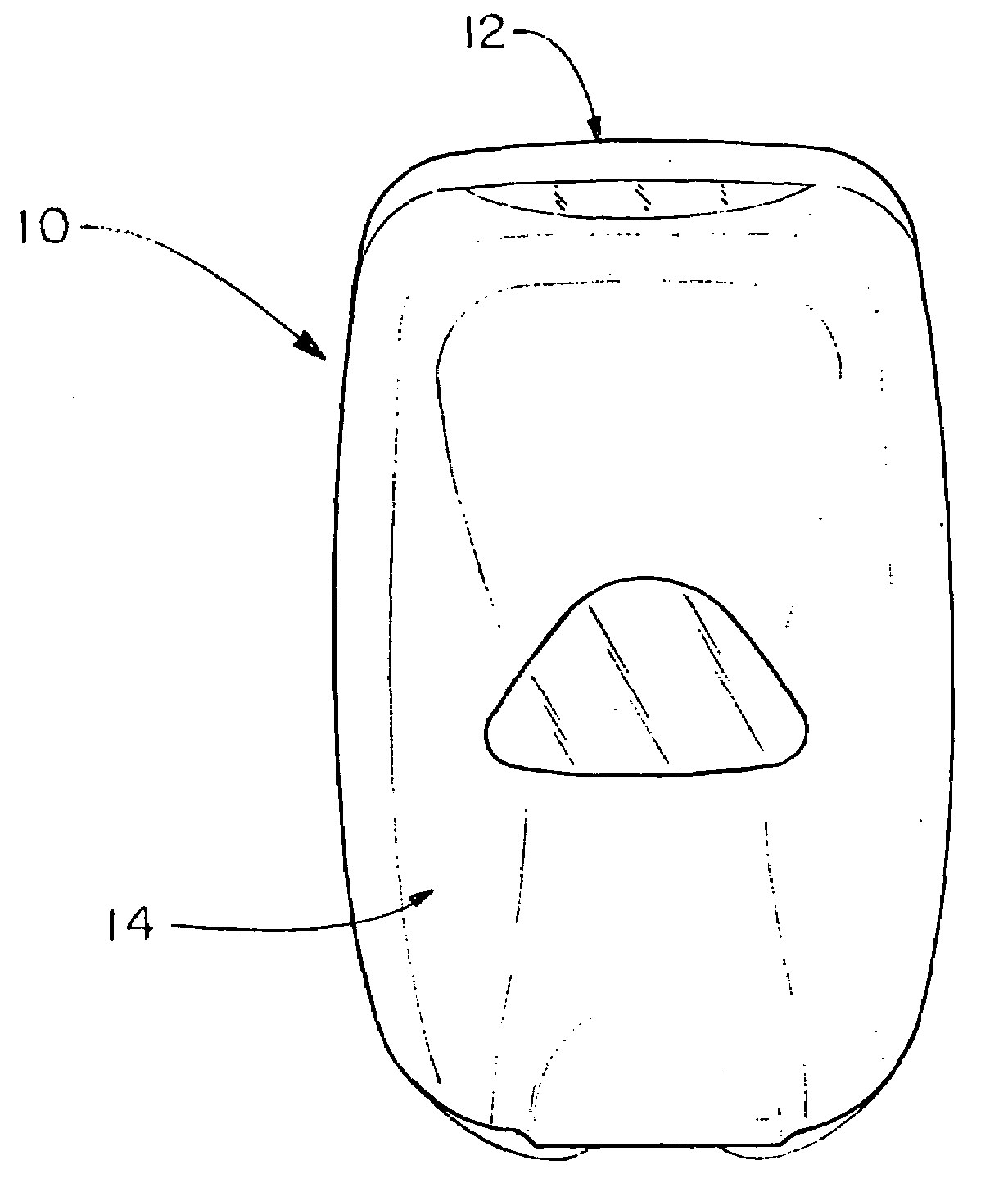
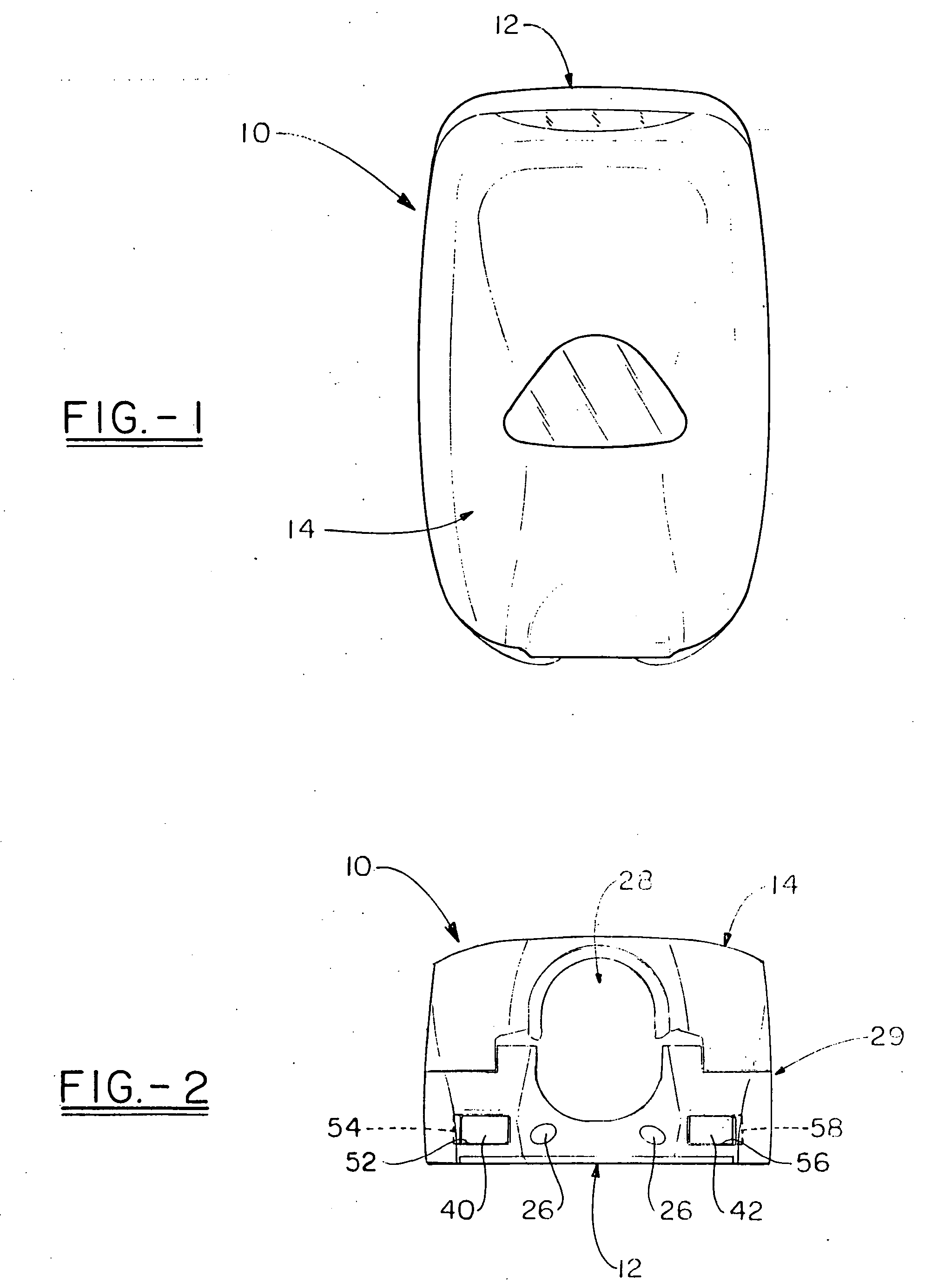
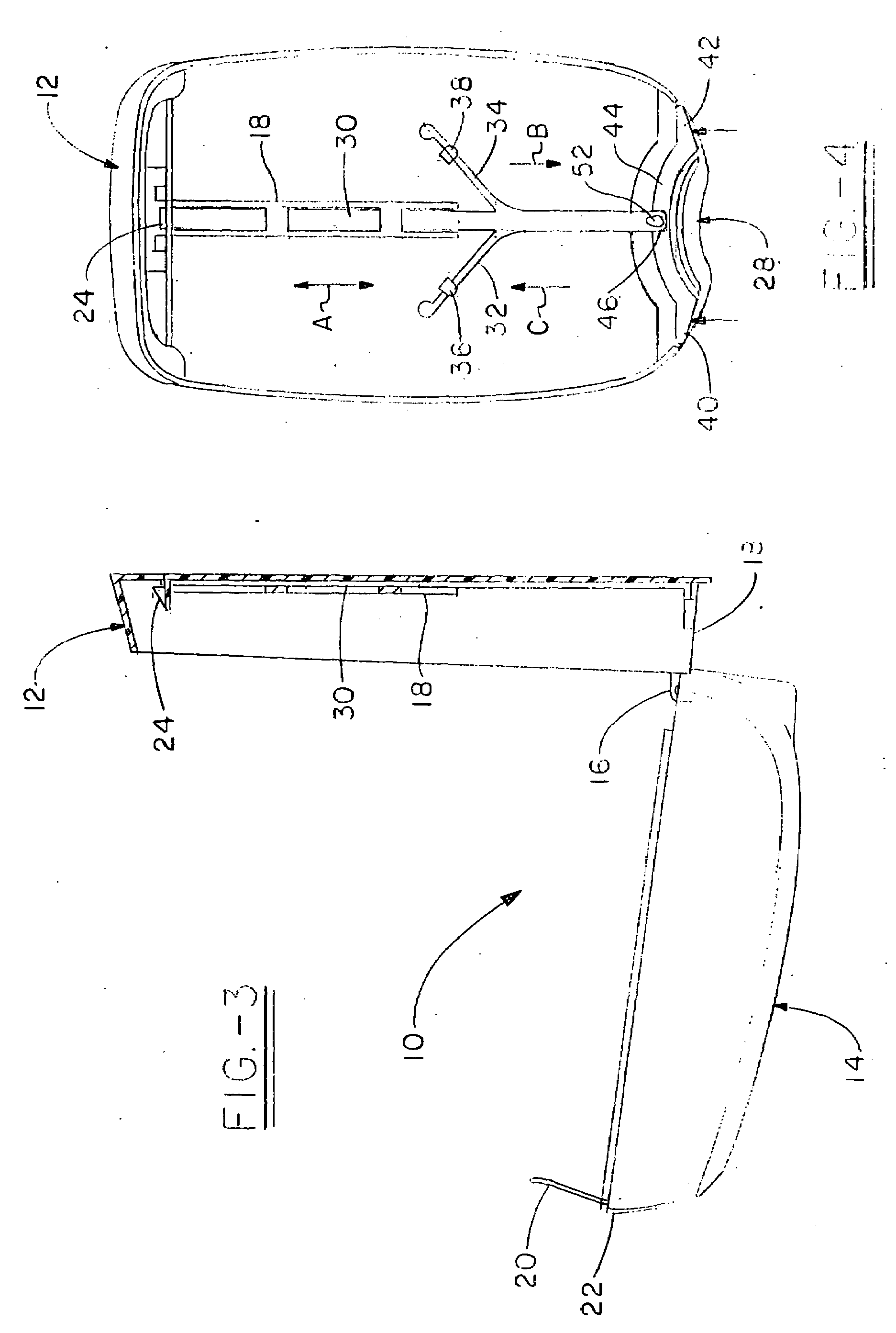
[0016]Referring first to FIGS. 1-4, a wall-mounted dispenser in accordance with this invention is shown and designated by the numeral 10. Dispenser 10 includes backplate 12, which is adapted for mounting to a wall structure as generally known in the wall-mounted dispenser arts. Cover 14 is pivotally secured to backplate 12, as at hinge 16, proximate bottom edge 18 of backplate 12. Cover 14 can pivot between a closed position, as shown in FIGS. 1 and 5, and an open position, as shown in FIG. 3. In the closed position, latch 20, which is associated with cover 14 and located near top edge 22 thereof, engages catch 24, which is associated with backplate 12, to keep dispenser 10 closed and ready for use. With reference to FIGS. 5 and 6, it can be seen that latch 20 includes an aperture 21 that receives catch 24 when cover 14 is closed on backplate 12. It should further be appreciated that latch 20 rides up on the sloped surface 25 of catch 24 as cover 14 is being closed upon backplate 12...


PUM


Abstract

A dispenser includes a cover pivotally secured to a backplate to move between an open position, at which the dispenser can be refilled, and a closed position, at which the dispenser may be actuated. The cover includes a latch that engages a catch held on the backplate. An elongate bar secured to the backplate is provided to engage the latch and remove it from the catch to permit the cover to be moved to the open position. The elongate bar includes a yoke extending to left and right terminal ends that are accessible outside of a dispensing zone of the dispenser. This invention is particularly applicable to dispensers that employ sensors to sense the presence of a hand at a dispensing zone.

Description

TECHNICAL FIELD[0001]This invention generally relates to dispensers, and, particularly, relates to cover release mechanisms for dispensers. This invention is found to be particularly useful in “hands-free” type wall-mounted dispensers that employ sensors to activate dispensing means rather than dispensing upon a user physically manipulating a portion of the dispenser.BACKGROUND OF THE INVENTION[0002]This invention relates particularly to wall-mounted dispensers of which there are a variety known to the art. In general, wall-mounted dispensers include a backplate and cover that is capable of being opened to permit the dispenser to receive replaceable cartridges or refill packages containing the desired material to be dispensed. These dispensers are more or less permanent installations in areas such as lavatories, restrooms, food handling areas, hospitals, etc. In some embodiments, the cover is pivotally secured to the backplate on a hinge such that the cover can pivot from a closed p...

Claims


Application Information

Patent Timeline
Patent Type & Authority Applications(United States)
IPC IPC(8): B67D5/08B67D5/06B67D7/08B67D7/06
CPCA47K5/12B67D7/06
Inventor ROSENKRANZ, MARK E.REYNOLDS, AARON R.QUINLAN, ROBERT L.
Owner KANFER JOSEPH S
Why Eureka
Try Eureka