
Liquid crystal device

a liquid crystal display and liquid crystal technology, applied in static indicating devices, instruments, non-linear optics, etc., can solve problems such as abnormal display, limit the practical application of tft liquid crystal screens, and abnormal displays

Active Publication Date: 2018-04-12
WISTRON CORP
View PDF4 Cites 0 Cited by
  • Summary
  • Abstract
  • Description
  • Claims
  • Application Information

AI Technical Summary

Benefits of technology

The technical effect of this patent is to provide a solution for the limitations of TFT liquid crystal screens in extreme temperature environments. The invention aims to maintain the high directivity and display quality of liquid crystal molecules in both low and high temperature environments, to expand the practical application of TFT liquid crystal screens.

Problems solved by technology

However, since liquid crystal molecules are solidified in an environment with a low temperature less than −20° C., it may make the solidified liquid crystal molecules incapable of twisting under the voltage difference applied by the thin film transistor, so as to cause abnormal display of the TFT liquid crystal screen.
On the other hand, if the TFT liquid crystal screen is operated in an environment with a high temperature higher than 70° C., each liquid crystal molecule would lose its high directivity due to melt of each liquid crystal molecule, so as to cause abnormal display of the TFT liquid crystal screen.
In summary, the aforesaid problems greatly limit the practical application of the TFT liquid crystal screen.

Method used


Image

  • Liquid crystal device
  • Liquid crystal device
  • Liquid crystal device

Examples


Embodiment Construction

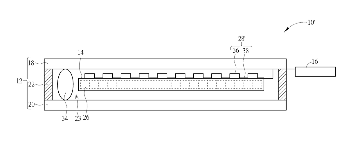
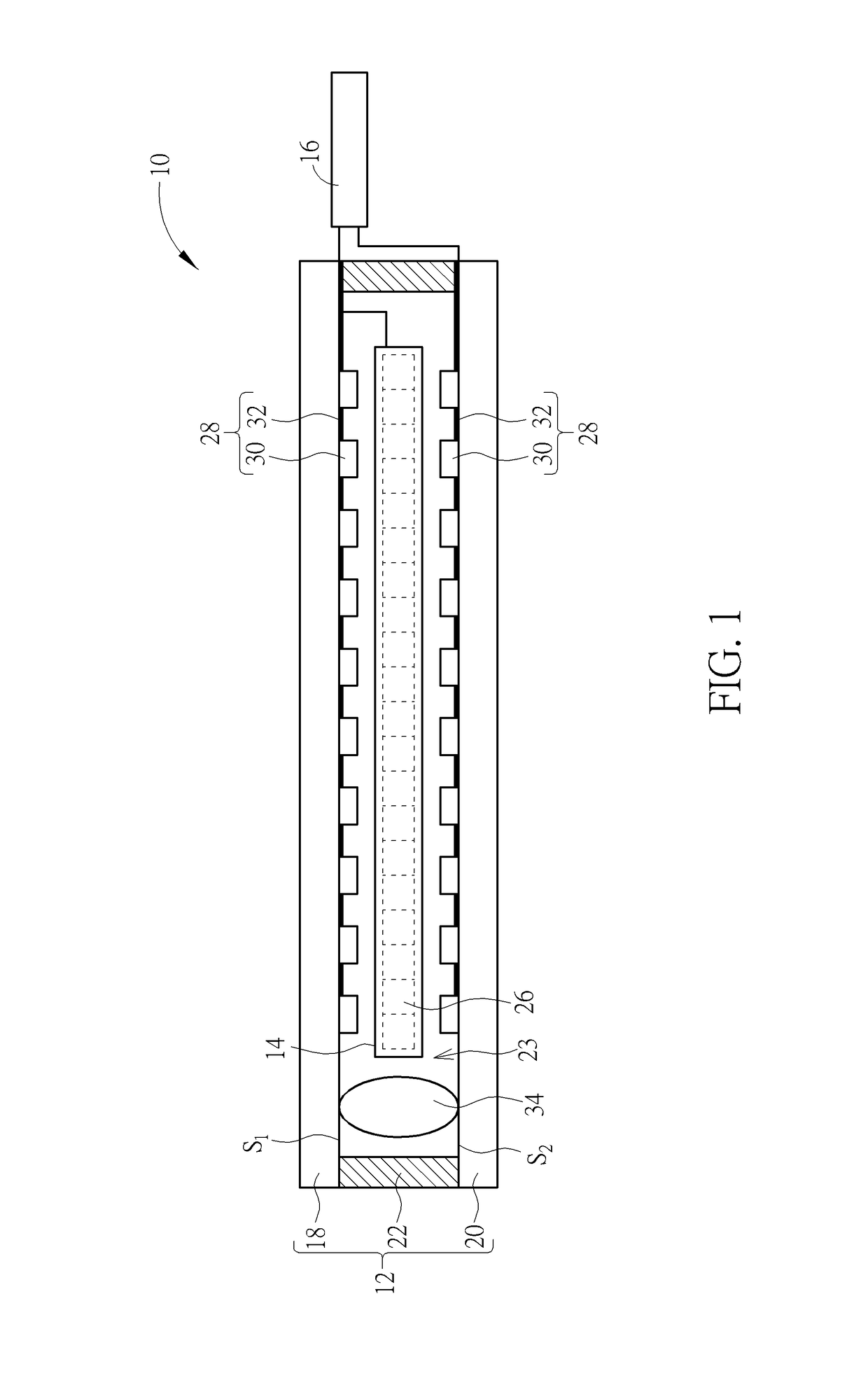
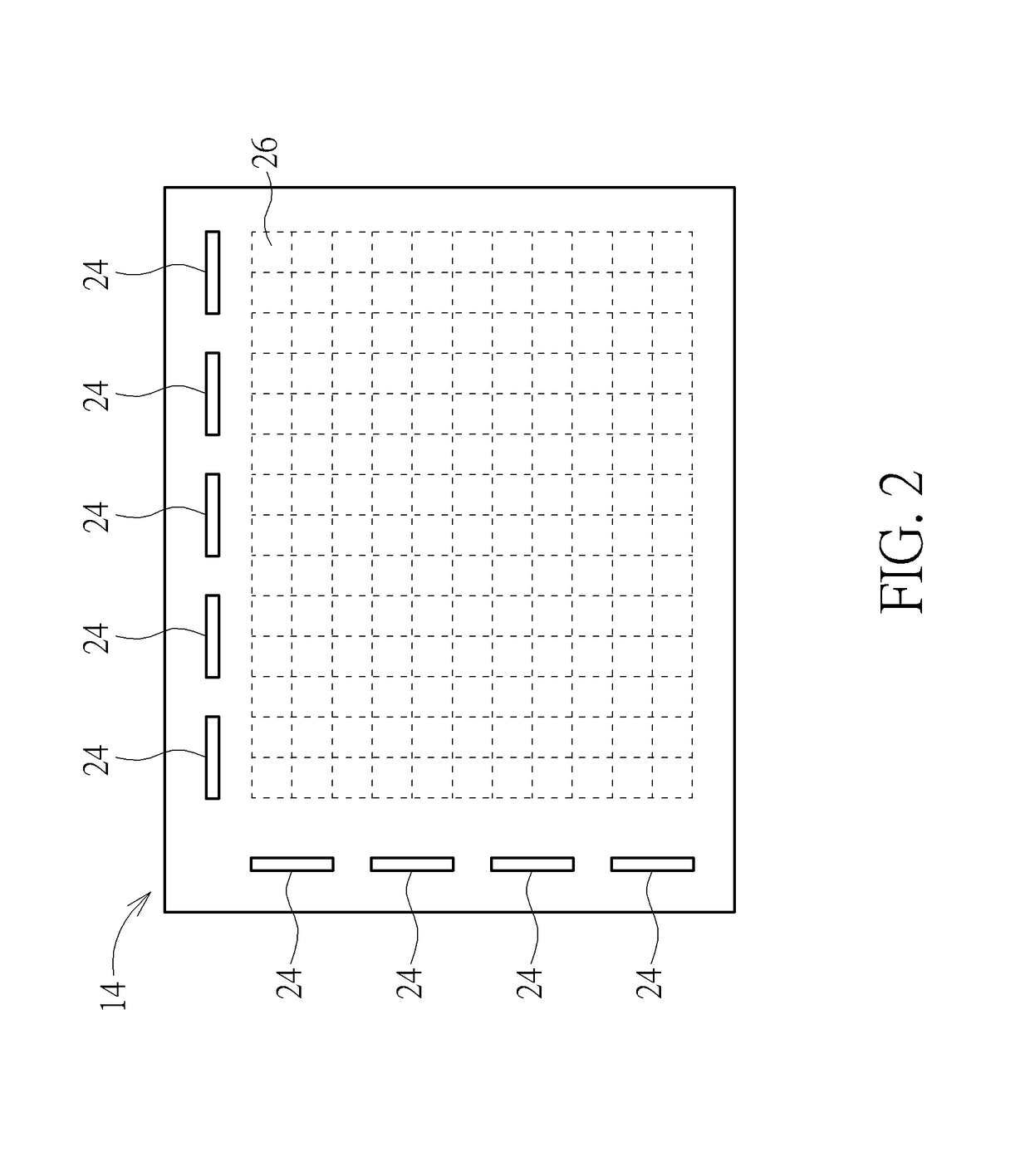
[0009]Please refer to FIG. 1 and FIG. 2. FIG. 1 is an internal diagram of a liquid crystal device 10 according to an embodiment of the present invention. FIG. 2 is a top view of a liquid crystal panel 14 in FIG. 1. As shown in FIG. 1 and FIG. 2, the liquid crystal device 10 could be preferably a TFT liquid crystal screen and includes a vacuum insulating structure 12, a liquid crystal panel 14, and a control circuit board 16. The vacuum insulating structure 12 includes a first glass sheet 18, a second glass sheet 20, and a sealant 22. The sealant could be preferably made of ultraviolet curing adhesive or thermoplastic material (but not limited thereto, meaning that it could vary with the practical manufacturing needs of the liquid crystal device 10), and could be attached to the first glass sheet 18 and the second sheet 20 for forming a vacuum space 23 cooperatively with the first glass sheet 18 and the second glass sheet 20 by a vacuum pumping process so that the liquid crystal pane...


PUM


Abstract

A liquid crystal device includes a vacuum insulating structure, a liquid crystal panel and a control circuit board. The vacuum insulating structure includes a first glass sheet, a second glass sheet, and a sealant. The sealant is attached between the first glass sheet and the second glass sheet for forming a vacuum space cooperatively with the first glass sheet and the second glass sheet by a vacuum pumping process. The liquid crystal panel is disposed in the vacuum space. The control circuit board is electrically connected to the liquid crystal panel for controlling the liquid crystal panel.

Description

BACKGROUND OF THE INVENTION1. Field of the Invention[0001]The present invention relates to a liquid crystal device, and more specifically, to a liquid crystal device having a vacuum insulating structure.2. Description of the Prior Art[0002]In general, an industrial computer or all-in-one computer operated in a special environment usually utilizes a TFT (Thin Film Transistor) liquid crystal screen for displaying images. However, since liquid crystal molecules are solidified in an environment with a low temperature less than −20° C., it may make the solidified liquid crystal molecules incapable of twisting under the voltage difference applied by the thin film transistor, so as to cause abnormal display of the TFT liquid crystal screen. On the other hand, if the TFT liquid crystal screen is operated in an environment with a high temperature higher than 70° C., each liquid crystal molecule would lose its high directivity due to melt of each liquid crystal molecule, so as to cause abnorm...

Claims


Application Information

Patent Timeline
IPC IPC(8): G02F1/1333G02F1/133G02F1/1345
CPCG02F1/133308G02F1/13306G02F1/13452G02F2001/133325G02F2201/50G02F2001/133331G02F1/133382G02F1/1333G02F1/133325G02F1/133331
Inventor CHANG, YAO-LIN
Owner WISTRON CORP
Learn More