Light source module and optical member

a technology of light source module and optical member, which is applied in the direction of lighting and heating apparatus, semiconductor devices of light sources, instruments, etc., can solve the problems of difficult to achieve uniform light emission, unsatisfactory light emission and life, and reduced brightness on the low voltage side, so as to enhance the light emission uniformity, enhance the light blocking ability, and sufficiently block light

Inactive Publication Date: 2012-08-30
SHARP KK
View PDF0 Cites 68 Cited by
  • Summary
  • Abstract
  • Description
  • Claims
  • Application Information

AI Technical Summary

Benefits of technology

[0049]An optical member of a second aspect of the present invention includes: a lighting curtain that partially blocks light; and a reflective layer that is provided on the lighting curtain and that has a planar shape smaller than the lighting curtain. In this configuration, since it is possible to enhance the light blocking ability in an area of the optical member, even if a large amount of light is applied to the area, it is possible to sufficiently block the light. Hence, when the optical member described above is used as the light source module, it is possible to enhance the uniformity of the light emitted from the light source module.
[0050]As described above, according to the present invention, it is possible to easily acquire a light source module that can illuminate a member to be illuminated without variations in brightness even when a light source having a high directivity is used or even when the thickness of the module is reduced.
[0051]According to the present invention, it is possible to easily acquire a light source module that can emit, even when a light source having a high directivity is used, uniform illumination light having variations in brightness reduced while reducing the thickness of the module.
[0052]According to the present invention, it is possible to easily acquire an optical member that has a sufficient blocking ability and that can improve the uniformity of light.

Problems solved by technology

However, when the CCFL is used as the light source of the light source module, the brightness of light emitted and the life are unsatisfactory.
Furthermore, disadvantageously, the brightness on a low voltage side is decreased, and thus it is difficult to achieve uniform light emission.
However, the lighting curtains disclosed in patent documents 1 to 3 do not always have their sufficient blocking ability.
Hence, when the lighting curtains disclosed in patent documents 1 to 3 are used in the conventional light source modules, the blocking ability is not sufficient, and thus an excessive amount of light passes through portions that need to block the light.
However, in this case, the increased thickness of the lighting curtain disadvantageously causes the thickness of the light source module to be increased.
Since the increased thickness of the reflective plate (the lighting curtain) makes it difficult to process the opening, it is disadvantageously difficult to obtain the lighting curtain (light source module) that can effectively reduce variations in brightness.
As disclosed in patent document 4, when a plurality of lighting curtains are stacked, it is possible to acquire a high blocking ability; however, even in this case, since the thickness of the lighting curtain is increased, the thickness of the light source module is disadvantageously increased.
Moreover, in this case, problems such as the displacement of positions between the lighting curtains and the increased number of assembly steps are newly produced.
Hence, the lighting curtains disclosed in patent documents 3 and 4 do not sufficiently function as solutions.
As described above, in the conventional light source module, when a light source having a high directivity is used or when the thickness of the module is reduced, it is disadvantageously difficult to obtain uniform illumination light.
In the conventional light source module, when a light source having a high directivity is used in order to obtain uniform illumination light, it is also disadvantageously difficult to reduce the thickness of the module.

Method used


Image

  • Light source module and optical member
  • Light source module and optical member
  • Light source module and optical member

Examples


first embodiment

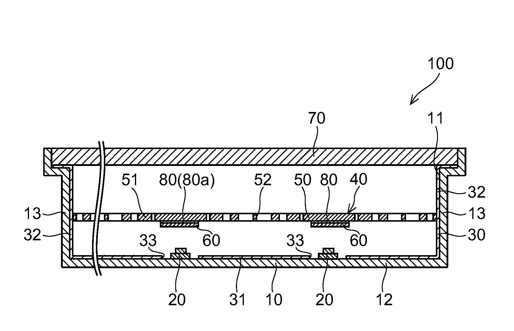
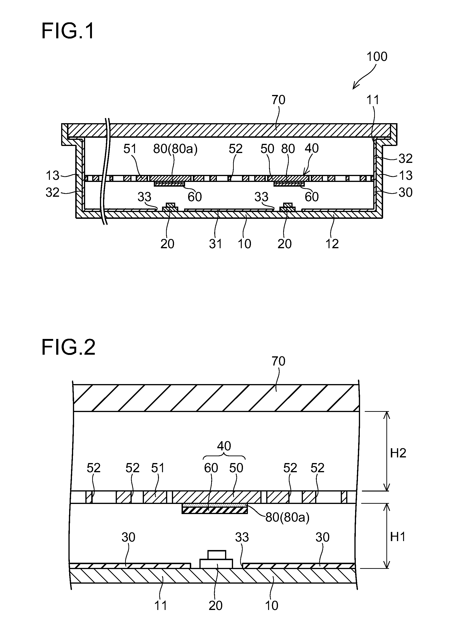
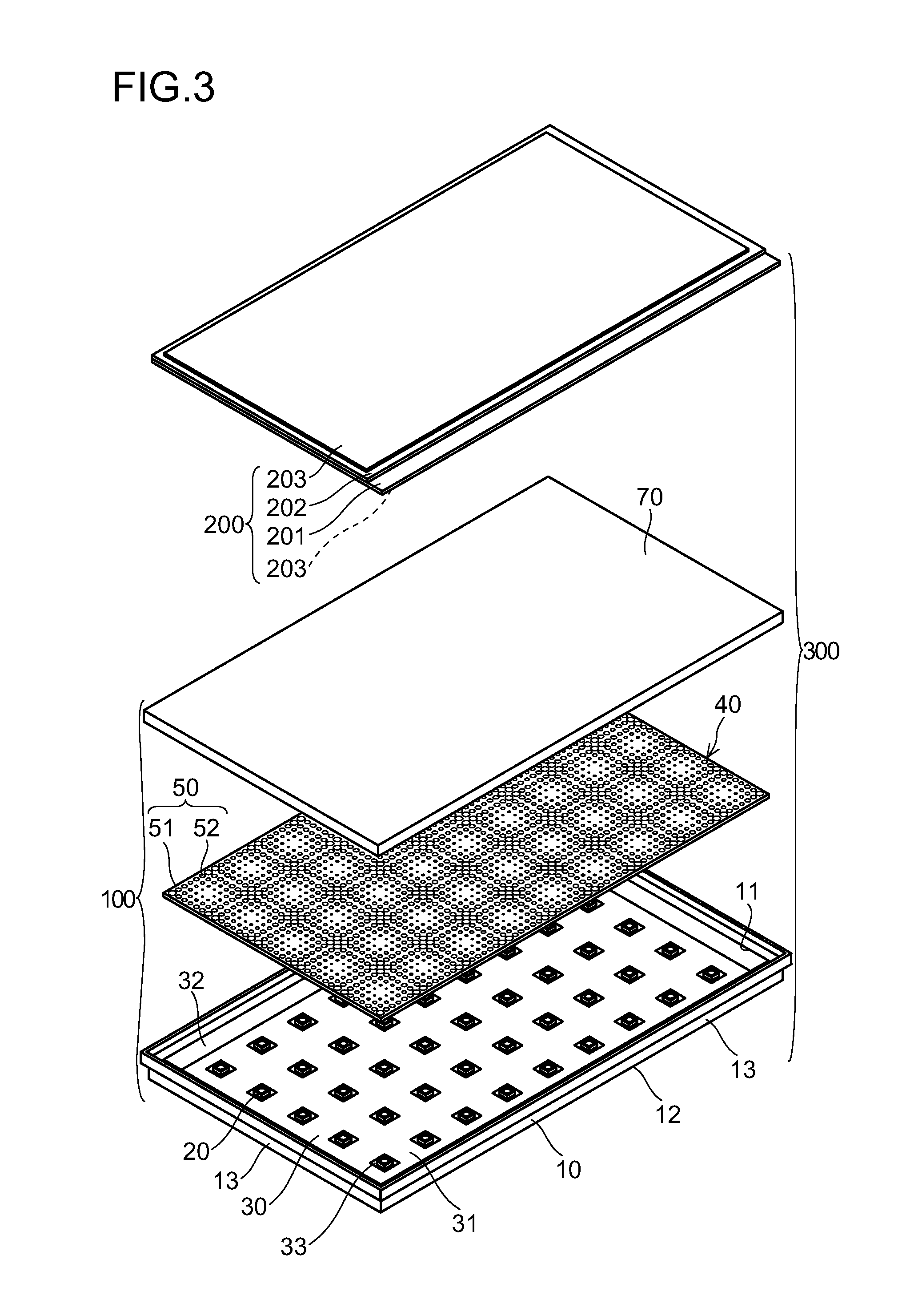
[0097]FIG. 1 is a cross-sectional view of a light source module according to a first embodiment of the present invention. FIG. 2 is a cross-sectional view showing an enlarged portion of FIG. 1. FIG. 3 is a perspective view schematically showing the light source module according to the first embodiment of the present invention. FIGS. 4 to 7 are diagrams illustrating the light source module according to the first embodiment of the present invention. The light source module according to the first embodiment of the present embodiment will first be described with reference to FIGS. 1 to 7.

[0098]As shown in FIGS. 1 to 3, the light source module 100 of the first embodiment is configured to include an enclosure 10, LED packages 20, a reflective sheet 30 and an optical member 40. The optical member 40 has a lighting curtain 50 and a plurality of reflective sheet segments 60 that are fixed to the lighting curtain 50. Above the lighting curtain 50, a diffusion plate 70 that diffuses light is a...

second embodiment

[0145]FIG. 12 is a cross-sectional view of a light source module according to a second embodiment of the present invention; FIG. 13 is a cross-sectional view showing an enlarged portion of FIG. 12. FIG. 14 is a perspective view of a reflective sheet segment of the light source module according to the second embodiment of the present invention; FIG. 15 is a plan view showing a portion of a lighting curtain in the light source module according to the second embodiment of the present invention. The light source module according to the second embodiment of the present invention will now be described with reference to FIGS. 12 to 15. In the drawings, the corresponding constituent components are identified with common symbols, and therefore their description will not be repeated as appropriate.

[0146]As shown in FIGS. 12 and 13, in the light source module 101 (100) of the second embodiment, the reflective sheet segments 61 (60) are configured to cover at least part of the openings 52 of th...

third embodiment

[0156]FIG. 16 is a cross-sectional view of a light source module according to a third embodiment of the present invention; FIG. 17 is a cross-sectional view showing an enlarged portion of FIG. 16. FIG. 18 is a perspective view of a reflective sheet segment of the light source module according to the third embodiment of the present invention; FIG. 19 is a plan view showing a portion of a lighting curtain in the light source module according to the third embodiment of the present invention. The light source module according to the third embodiment of the present invention will now be described with reference to FIGS. 16 to 19. In the drawings, the corresponding constituent components are identified with common symbols, and therefore their description will not be repeated as appropriate.

[0157]As shown in FIGS. 16 and 17, in the light source module 102 (100) of the third embodiment, opening holes 61a common to the lighting curtain 50 are formed in part of the reflective sheet segments 6...


PUM


Abstract

A light source module includes: a light source; a lighting curtain that partially blocks light from the light source; and a reflective layer that is provided on the lighting curtain and that has a planar shape smaller than the lighting curtain.

Description

[0001]This application is based on Japanese Patent Application No. 2011-038050 filed on Feb. 24, 2011, the contents of which are hereby incorporated by reference.BACKGROUND OF THE INVENTION[0002]1. Field of the Invention[0003]The present invention relates to a light source module and an optical member that is used in the light source module.[0004]2. Description of the Related Art[0005]Conventionally, there is known a light source module that generates planar illumination light and that illuminates a member to be illuminated; the light source module is used as a backlight unit arranged in a liquid crystal display device or the like (for example, see patent document 1).[0006]Conventionally, as a light source of the light source module, a CCFL (cold cathode fluorescent lamp) that seals mercury or xenon in a fluorescent lamp or the like is mainly used. However, when the CCFL is used as the light source of the light source module, the brightness of light emitted and the life are unsatisf...

Claims


Application Information

Patent Timeline
Patent Type & Authority Applications(United States)
IPC IPC(8): F21V11/00
CPCF21K9/54F21S2/00F21V7/22F21V11/14G02B5/00G02F2202/28F21Y2101/02G02F1/133603G02F1/133606G02F1/133605G02F1/133611G02B5/08F21K9/62F21Y2115/10
Inventor SUMITANI, KEN
Owner SHARP KK
Why Eureka
Try Eureka