Directional coupler and dual-band transmitter using the same

a dual-band transmitter and directional coupler technology, applied in the direction of transmission monitoring, waveguide type devices, modulation, etc., can solve the problems of complex circuit implementation, inability to finely control power, and degrading amplifier efficiency, so as to improve directivity, minimize process errors, and facilitate implementation

Inactive Publication Date: 2007-03-06
SAMSUNG ELECTRONICS CO LTD
View PDF12 Cites 71 Cited by
  • Summary
  • Abstract
  • Description
  • Claims
  • Application Information

AI Technical Summary

Benefits of technology

[0028]Therefore, the present invention has been made in view of the above problems, and it is an object of the present invention to provide a directional coupler which is implemented with strip lines for signal coupling and inter-digital capacitors for phase compensation so that it can be improved in directivity, minimized in process error and miniaturized to be readily implemented in one-chip form, and a dual-band transmitter using the same.

Problems solved by technology

The closed loop method is a traditional method and has the advantage of being able to finely control power, but the disadvantage of involving complexity in circuit implementation and degrading efficiency of the amplifier due to a loss by the coupler.
The open loop method is currently often used in that it involves simplicity in circuit implementation, but has the disadvantage of being unable to finely control power.
However, since the coupling port is used in common for the two bands in the conventional directional coupler for the dual-band transmitter to reduce the chip size of the coupler, there is a problem in that an inter-band isolation is reduced in the dual-band transmitter.
However, the above-mentioned conventional filter-type directional coupler is disadvantageous in that it is increased in chip size and degraded in directivity, as will hereinafter be described with reference to FIGS. 4a to 4d.
As a result, the conventional filter-type directional coupler has the disadvantage of not being good in directivity and the disadvantage of being increased in chip size.

Method used


Image

  • Directional coupler and dual-band transmitter using the same
  • Directional coupler and dual-band transmitter using the same
  • Directional coupler and dual-band transmitter using the same

Examples


Embodiment Construction

[0040]Now, preferred embodiments of the present invention will be described in detail with reference to the annexed drawings.

[0041]In the drawings, the same or similar elements are denoted by the same reference numerals even though they are depicted in different drawings.

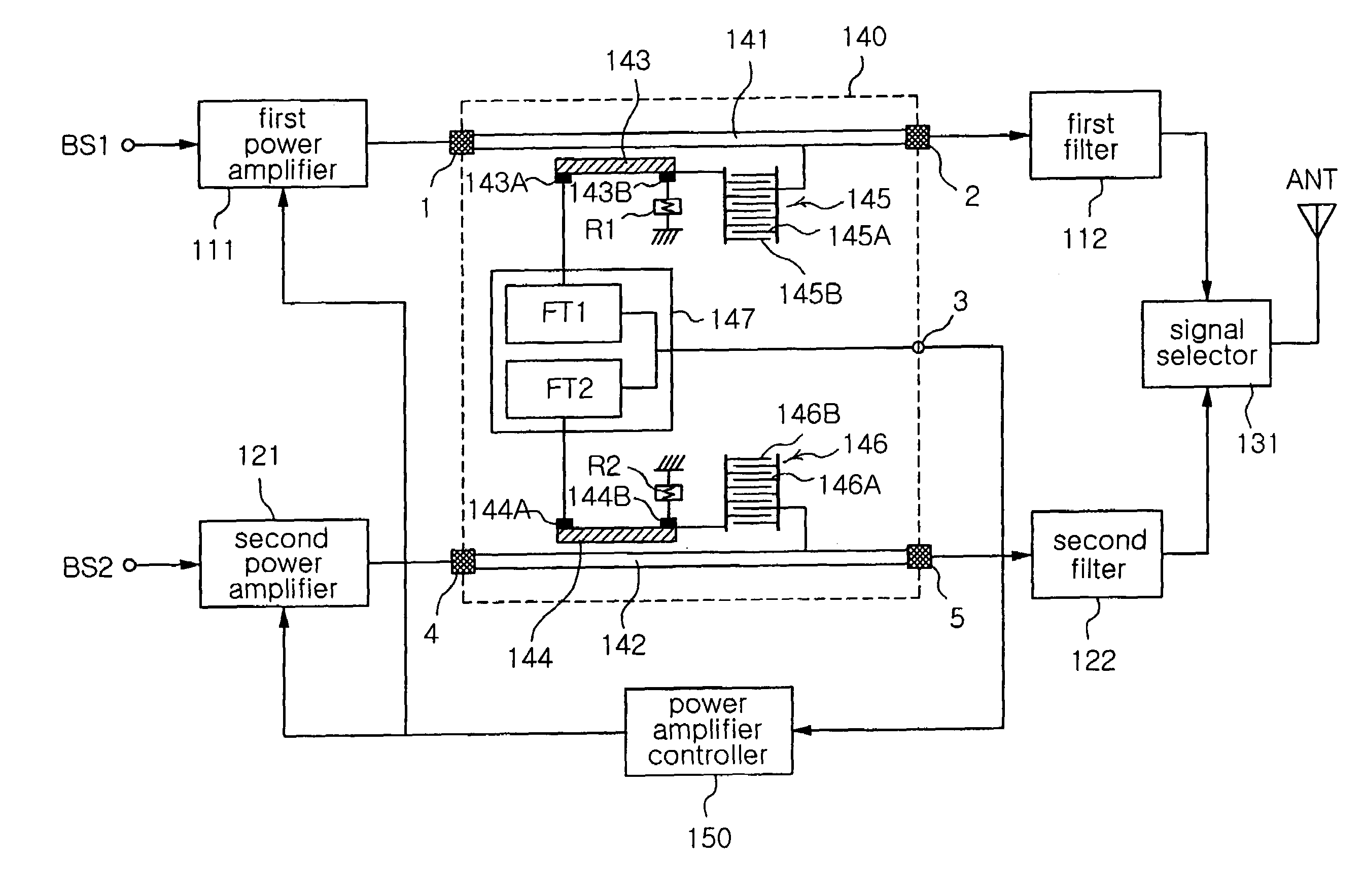
[0042]FIG. 5 shows the configuration of a directional coupler according to the present invention.

[0043]With reference to FIG. 5, the directional coupler according to the present invention, denoted by the reference numeral 140, comprises a first transmission device 141 having a first port 1 and second port 2 to transmit a first band signal, and a first directional coupling device 143 including a first terminal 143A and second terminal 143B and spaced apart from the first transmission device 141 by a predetermined distance. The first directional coupling device 143 couples a part of the first band signal from the first transmission device 141 and generates the coupled signal at the first terminal 143A thereof. The sec...


PUM


Abstract

Disclosed herein are a directional coupler which is implemented with strip lines for signal coupling and inter-digital capacitors for phase compensation, and a dual-band transmitter using the same. The directional coupler includes a first transmission device, a first directional coupling device for coupling a part of a signal from the first transmission device, a first inter-digital capacitor connected between the first transmission device and the first directional coupling device, a second transmission device, a second directional coupling device for coupling a part of a signal from the second transmission device, and a second inter-digital capacitor connected between the second transmission device and the second directional coupling device.

Description

BACKGROUND OF THE INVENTION[0001]1. Field of the Invention[0002]The present invention relates to a directional coupler which is applied to a dual-band mobile communication terminal such as a dual-band mobile phone, and more particularly to a directional coupler which is implemented with strip lines for signal coupling and inter-digital capacitors for phase compensation so that it can be improved in directivity, minimized in process error and miniaturized to be readily implemented in one-chip form, and a dual-band transmitter using the same.[0003]2. Description of the Related Art[0004]In general, a power amplifier is used in a transmitter of a mobile communication terminal, such as a mobile phone, to amplify power of a transmit signal to be sent out through an antenna of the terminal. This power amplifier has to amplify the transmit signal to an appropriate power level. Methods for regulating output power of the power amplifier can be roughly classified into two types, a closed loop ...

Claims


Application Information

Patent Timeline
Patent Type & Authority Patents(United States)
IPC IPC(8): H04B1/02H01P5/00H01P5/18H01Q11/12H04B1/04
CPCH01P5/185H01P5/18
Inventor KIM, KI JOONGHUR, DAE HEONBYUN, WOO JIN
Owner SAMSUNG ELECTRONICS CO LTD
Why Eureka
Try Eureka