Multilayer Broadband Microstrip Antenna

A microstrip antenna and broadband technology, which is applied in the field of radiation terminals, can solve the problems of antenna pattern performance degradation and affect the application of microstrip antennas, and achieve the effects of improving antenna pattern characteristics, increasing bandwidth, and easy processing

Inactive Publication Date: 2011-12-28
JIMEI UNIV
View PDF5 Cites 66 Cited by
  • Summary
  • Abstract
  • Description
  • Claims
  • Application Information

AI Technical Summary

Problems solved by technology

However, the use of slot coupling technology and stacking technology will inevitably change the original radiation structure of the antenna, arouse interference factors such as surface waves, and cause back lobes and side lobes on the pattern, which will bring about a decline in the performance of the antenna pattern and affect the microstrip antenna. Application in some strong directivity scenes

Method used


Image

  • Multilayer Broadband Microstrip Antenna
  • Multilayer Broadband Microstrip Antenna
  • Multilayer Broadband Microstrip Antenna

Examples


Embodiment Construction

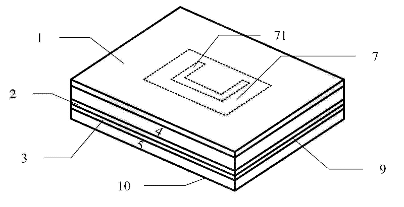
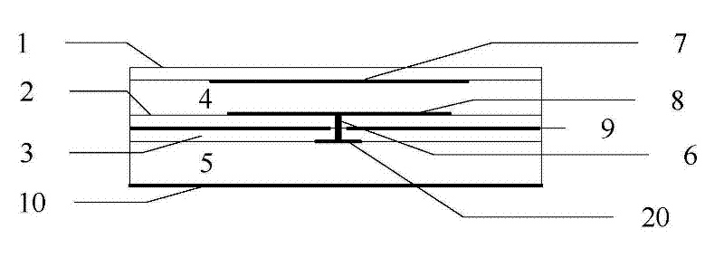
[0026] Such as figure 1 , figure 2 As shown, the present invention is a multilayer broadband microstrip antenna, which includes an upper dielectric substrate 1, an intermediate dielectric substrate 2, a lower dielectric substrate 3, an upper low dielectric constant insulating dielectric layer 4, and a lower low dielectric constant insulating dielectric Layer 5, feeding probe 6, upper rectangular metal patch 7, middle rectangular metal patch 8, metal ground layer 9, reflector 10.

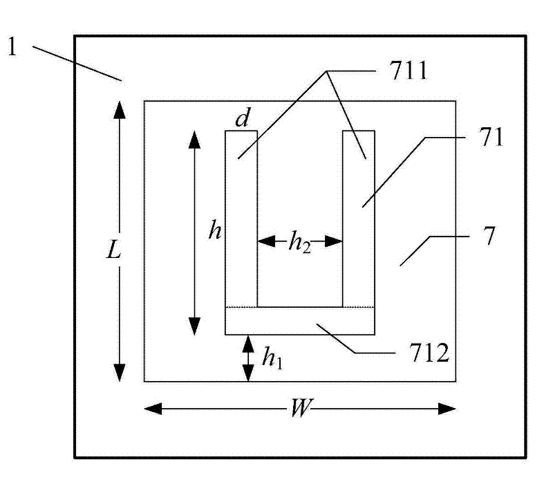
[0027] The lower surface of the upper dielectric substrate 1 is attached with an upper rectangular metal patch 7 as a radiator, and the upper rectangular metal patch 7 is provided with a U-shaped groove 71 (such as image 3 shown). The upper surface of the intermediate dielectric substrate 2 is also attached with a middle rectangular metal patch 8 as a coupler, and the middle rectangular metal patch 8 is provided with a U-shaped groove 81 (such as Figure 4 As shown), its size is different from t...


PUM


Abstract

The invention discloses a multilayer broadband microstrip antenna, comprising an upper dielectric baseplate, a middle dielectric baseplate, a lower dielectric baseplate, an upper low dielectric constant insulating dielectric layer, a lower low dielectric constant insulating dielectric layer, a reflection plate and a feed probe, wherein rectangle radiators of metallic copper pasters are arranged on the lower surface of the upper dielectric baseplate and the upper surface of the middle dielectric baseplate and provided with U-shaped slot structures with different sizes respectively. Due to a special double-layer inverted U-shaped slot coupling feed way, the symmetry of directional diagrams on an E surface or H surface of the antenna is good, thus ensuring that the antenna has more consistent performances in more directions, and having more actual meanings as an exploration antenna and a communication antenna. The reflection plate with an EBG (electromagnetic band gap) structure can preferably restrain backward radiation in the specified frequency relative to a traditional metal reflection plate, thus improving the directivity of the antenna, thereby further improving the gain of theantenna.

Description

technical field [0001] The invention relates to a radiation terminal of a double-conductor microwave transmission line, in particular to a multilayer broadband microstrip antenna. Background technique [0002] Wireless local area network is the product of the combination of computer network and wireless communication technology. It uses wireless technology to replace all the functions of the traditional wired LAN, making the networking and use of the LAN more flexible and convenient. [0003] IEEE802.11 is one of the first generation wireless LAN standards. This standard defines the specifications of the physical layer and the media access control (MAC) protocol, allowing manufacturers of wireless local area networks and wireless equipment to establish interoperable network equipment within a certain range. There are multiple protocol groups under this standard, among which IEEE802.11a, IEEE802.11n, IEEE802.11p and other extended protocols can work in the 5GHz-6GHz frequen...

Claims


Application Information

Patent Timeline
Patent Type & Authority Applications(China)
IPC IPC(8): H01Q1/38H01Q13/08H01Q19/10H01Q15/14
Inventor 陈彭
Owner JIMEI UNIV
Why Eureka
Try Eureka