Automatic work system, and automatic walking device and steering method thereof

A technology of automatic walking equipment and working range, applied in control/regulation systems, motor vehicles, non-electric variable control, etc., can solve problems such as unreasonable judgment, low work efficiency, and inability to know the exact position of the original walking direction.

Pending Publication Date: 2016-08-31
POSITEC POWER TOOLS (SUZHOU) CO LTD
View PDF5 Cites 15 Cited by
  • Summary
  • Abstract
  • Description
  • Claims
  • Application Information

AI Technical Summary

Problems solved by technology

Most of the commercial automatic working devices use random paths, that is, they travel along a straight line within the working range. When encountering obstacles or boundary lines, they first brake to stop walking, then turn randomly or according to a predetermined program, and then start to leave , the automatic working device can only sense that it has encountered an obstacle or boundary, but it cannot know its original walking direction and its exact position in the work area, so it cannot reasonably judge which direction to turn to next is the optimal solution, resulting in In a narrow area, you can only bump randomly. It takes a long time to leave the area, and you may even be unable to leave; at the same time, because you cannot judge where to turn next, the automatic working device needs to stop walking before turning instead of turning directly. In addition, the working area of ​​the automatic walking equipment for home use is not large, and it will soon walk from one end to the other end, causing the automatic walking equipment to stop and start continuously during the entire working process, unable to continue walking, and a lot of time wasted on stopping and starting , which greatly reduces the overall walking speed, resulting in low work efficiency, and also increases the mechanical wear of the automatic walking equipment, reducing the service life

Method used


Image

  • Automatic work system, and automatic walking device and steering method thereof
  • Automatic work system, and automatic walking device and steering method thereof
  • Automatic work system, and automatic walking device and steering method thereof

Examples


Embodiment Construction

[0137] Specific embodiments of the present invention will be described in detail below in conjunction with the accompanying drawings.

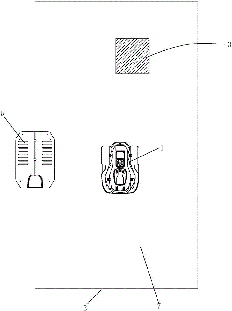
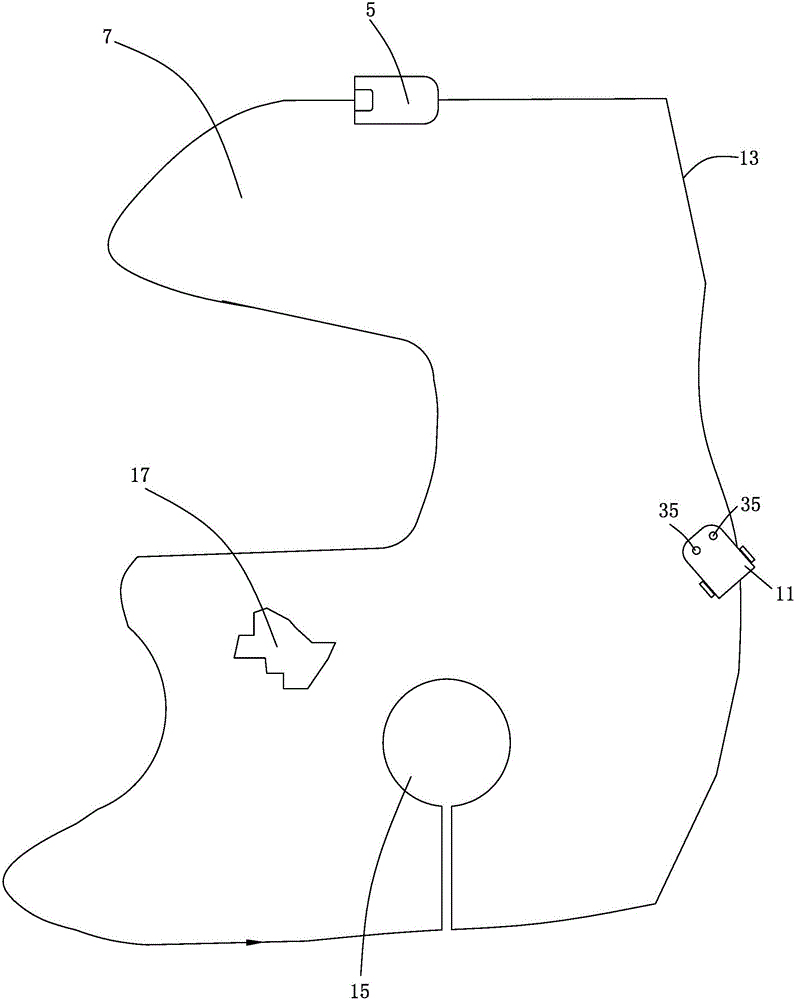
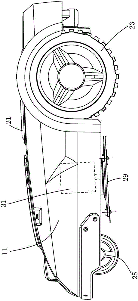
[0138] like figure 1 , The automatic working system of this specific embodiment includes an automatic running device 1 , a boundary line 3 and a stop 5 . Wherein the limit 3 is used to limit the working area 7 of the automatic working system, the automatic running equipment walks and works in or between the boundaries, and the docking station is used for parking the automatic running equipment, especially returning to replenish energy when the energy is insufficient.

[0139] Boundary is a general term for boundaries and barriers. The boundary is the periphery of the entire work area, usually connected end to end, and closes the work area. The boundary can be physical or electronic, that is, the boundary can be formed by walls, fences, railings, etc., or a virtual boundary can be sent by a boundary signal generator Signals, such as electroma...


PUM


Abstract

The invention provides an automatic walking device. The automatic walking device comprises a housing; a walking module installed at a housing; a boundary detection module installed at the housing for detecting a distance between the automatic walking device and a boundary; an energy module installed on the housing for providing energy for the automatic walking device; and a control module which is electrically connected with the walking module and the boundary detection module, according to signals representing an angle relation between the automatic walking device and the boundary, sent by the boundary detection module, makes the walking module execute steering, and enables a central axis of the automatic walking device to always form an acute angle or a right angle with one side edge of the boundary when the steering is finished and the other side of the boundary to form an acute angle or a right angle with the central axis of the automatic walking device when the steering begins. Steering walking is directional, going out of a narrow area can be easier, and the area coverage efficiency is higher.

Description

technical field [0001] The invention relates to the field of intelligent control, in particular to a steering method comprising automatic running equipment, an automatic working system and the automatic running equipment. Background technique [0002] With the continuous advancement of computer technology and artificial intelligence technology, automatic working systems similar to intelligent robots have begun to slowly enter people's lives. Companies such as Samsung and Electrolux have developed fully automatic vacuum cleaners and have put them into the market. This kind of fully automatic vacuum cleaner is usually small in size and integrates environmental sensors, self-driving system, vacuum system, battery and charging system. It can cruise indoors by itself without manual control, and automatically return to the charging station when the energy is low, docking and charging. Then go on cruise vacuuming. At the same time, companies such as Haskovana have developed simil...

Claims


Application Information

Patent Timeline
Patent Type & Authority Applications(China)
IPC IPC(8): G05D1/02
CPCG05D1/0212G05D2201/0217
Inventor 强尼·鲍瑞那图
Owner POSITEC POWER TOOLS (SUZHOU) CO LTD
Why Eureka
Try Eureka