

Planar Light Emitting Element, Image Display Element, and Image Display Device Using the Same
- Summary
- Abstract
- Description
- Claims
- Application Information
AI Technical Summary
Benefits of technology
Problems solved by technology
Method used
Image

Examples
first embodiment
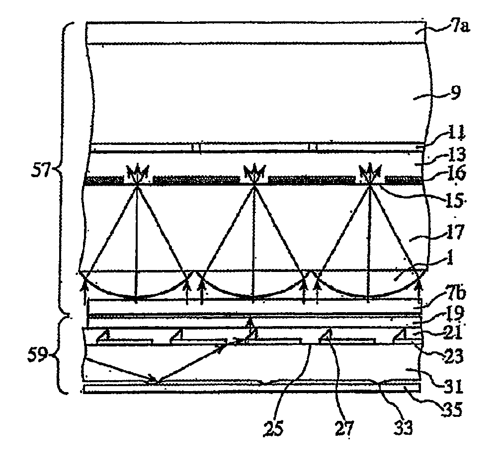
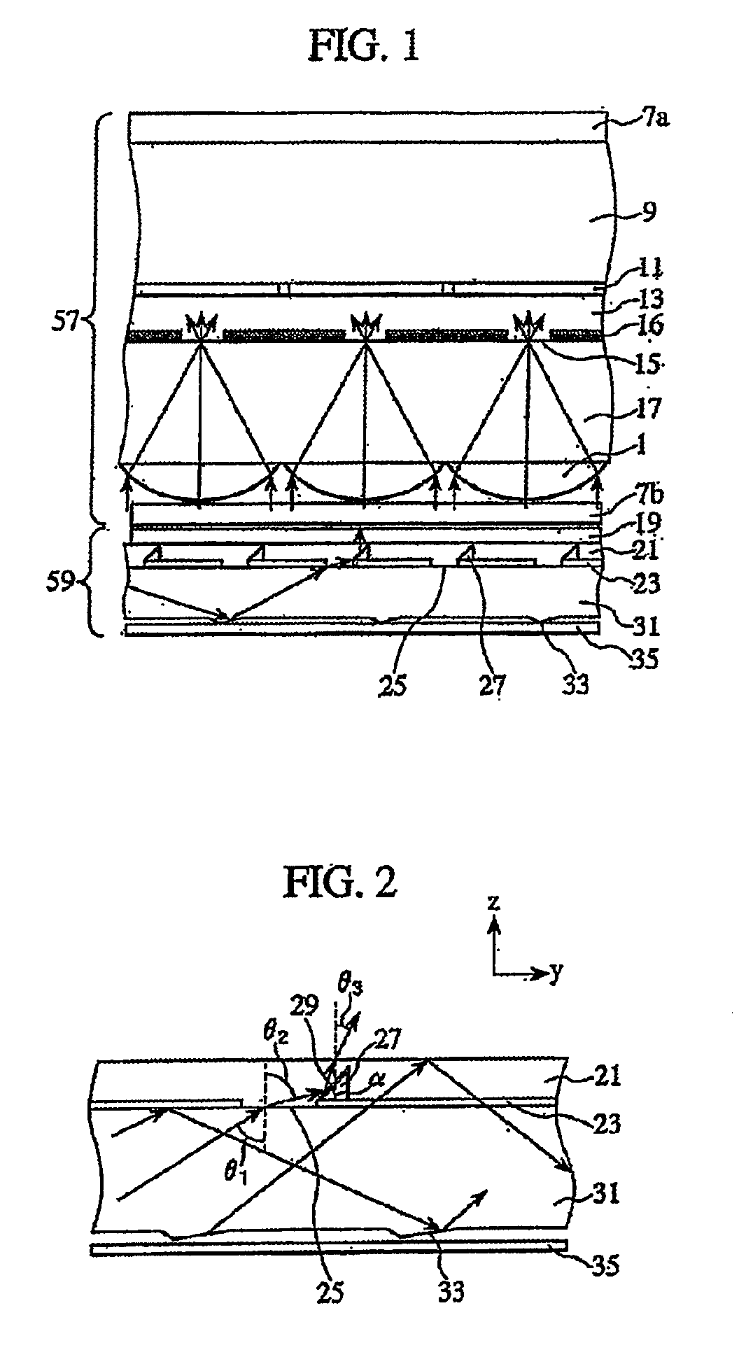
[0071]A description will be made of the present invention with reference to FIGS. 1 to 7C.
[0072]FIG. 1 is a cross sectional view of a planar light emitting element and an image display element, which constitute an image display device. FIG. 1 shows a transflective liquid crystal display element 57 and a backlight 59. The liquid crystal display element 57 serves as the image display element for displaying an image. The backlight 59 serves as the planar light emitting element for illuminating light emitted by a light source on the image display element. The backlight 59 is used for a liquid crystal display device.
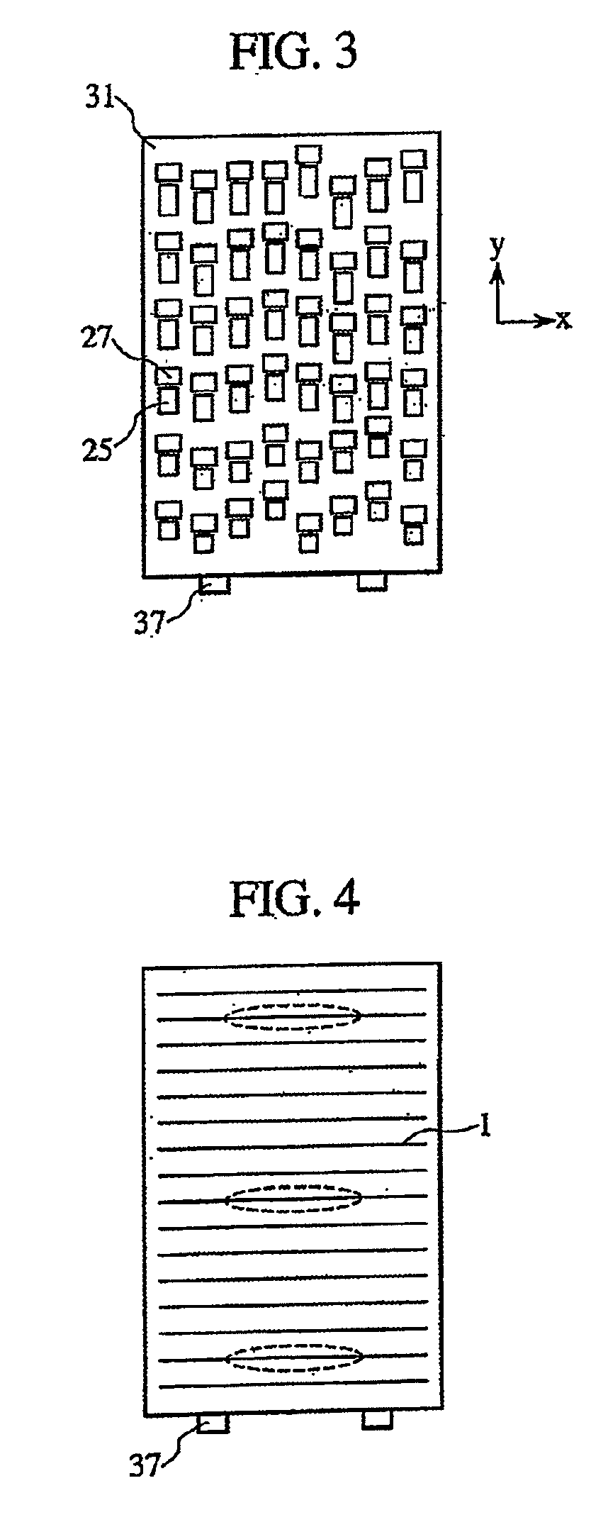
[0073]Referring to FIG. 1, a light guide plate 31 receives light emitted by the light source (not shown). The light is repeatedly reflected in the light guide plate 31. The light guide plate 31 has a reflective groove 33 on a lower side thereof, that is, on the side opposite to the liquid crystal display element 57 (the reflective groove 33 is provided on the side opposite to...
eighth embodiment
[0161]Next, a description will be made of the present invention with reference to FIGS. 21 to 23.
[0162]FIG. 21 is a cross sectional view of a planar light emitting element according to the eighth embodiment. Light incident on the light guide plate 31 from a light source (not shown) is mostly reflected multiple times within the light guide plate 31. The low refractive index layer 24 is provided on the side of the liquid crystal display element 57 with respect to the light guide plate 31 (and on the side of the light output surface of the light guide plate 31). Light is totally reflected on the interface between the light guide plate 31 and the low refractive index layer 24 and propagates in the light guide plate 31. In addition, light is totally reflected on the surface (located on the side of the liquid crystal display element 57) of the low refractive index layer 24 and propagates in the low refractive index layer 24.
[0163]A protruding sheet 49 having a protrusion 47 is provided to...
eleventh embodiment
[0183]Next, a description will be made of the present invention with reference to FIGS. 31 to 33.
[0184]FIG. 31 is a cross sectional view of a planar light emitting element and an image display element according to the eleventh embodiment. FIG. 32 is a cross sectional view of the planar light emitting element according to the eleventh embodiment. The image display element according to the eleventh embodiment is the same as the image display element according to the first embodiment. In the planar light emitting element according to the eleventh embodiment, the prism array provided in the first low refractive index layer 21 according to the second embodiment is separated from the first low refractive index layer 21; the prism sheet 41 is provided in place of the prism array; and a prism sheet 42 having a λ / 2 plate 67 is provided. Other portions of the planar light emitting element according to the eleventh embodiment are the same as the planar light emitting element (backlight 59) acc...
PUM
 Abstract
Description
Claims
Application Information