

Antenna module
- Summary
- Abstract
- Description
- Claims
- Application Information
AI Technical Summary
Benefits of technology
Problems solved by technology
Method used
Image

Examples
embodiment 1
(Embodiment 1)
[0074] Referring to FIGS. 1 to 10, first, the shape and structure of an antenna module will be explained and thereafter, its operation and advantage will be explained.
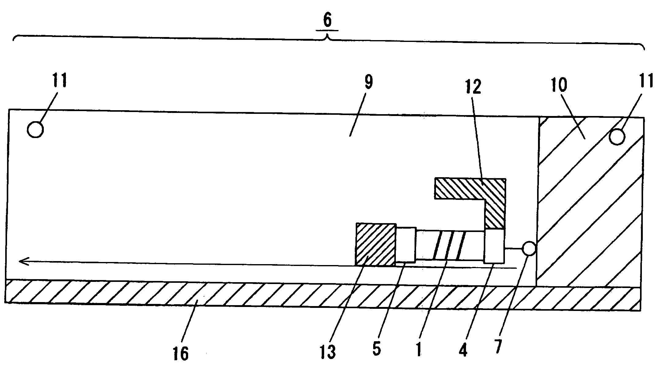
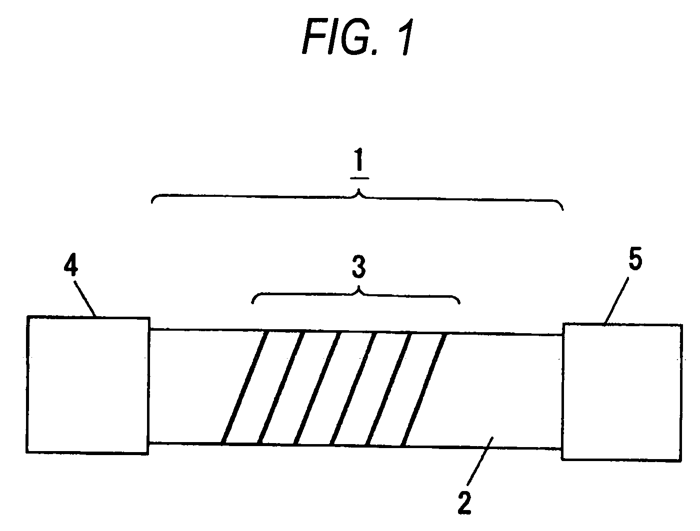
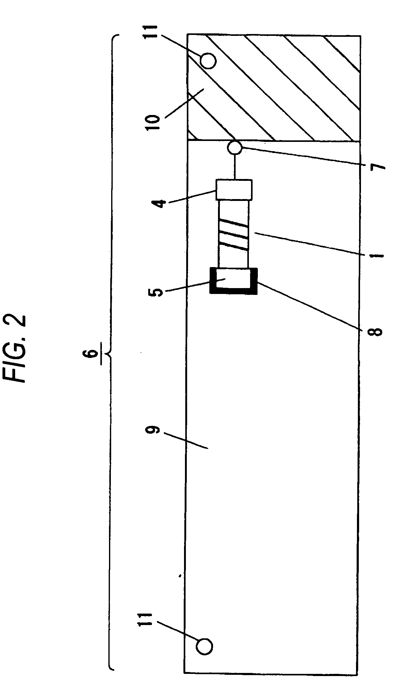
[0075]FIG. 1 is a view showing the structure of a helical antenna according to the first embodiment of this invention. FIGS. 2 to 10 are views showing the arrangement of the antenna module according to the first embodiment of this invention.
[0076] In these figures, reference numeral 1 denotes a helical antenna; 2 a base; 3 a helical segment; 4, 5 a terminal; 6 antenna module; 7 a power supply; 8 an opening; 9 an antenna substrate; 10 a grounding area; 11 a bonding slot; 12 a pattern antenna; 13 a top-up conductor; 14 an additive conductor, 15 a bottom conductor; 16 a peripheral conductor; 17 a peripheral length; and 18, 19 an additive conductor for adjustment.
[0077] First, the details of each component will be explained and its modification or advantage will be explained.
[0078] Referring to FIG. 1, th...
embodiment 2
(Embodiment 2)
[0149] In the second embodiment, an explanation will be given of realization of both downsizing and high performance of the antenna module 6 when it is arranged in a mounting dent formed in a box for an electronic device. The explanation will be also given of the electronic device in which the antenna module has been built.
[0150] FIGS. 12 to 14 are views showing the arrangement of the antenna module according to the second embodiment of this invention. FIG. 15 is a top view of the antenna module according to the second embodiment of this invention. FIGS. 16 and 17 are graphs showing experimental results in the antenna module according to the second embodiment of this invention. FIG. 18 is a perspective view of a notebook personal computer according to the second embodiment of this invention. FIG. 19 is a view showing the arrangement of a portable terminal according to the second embodiment of this invention.
[0151] In these figures, reference numeral 30 denotes an ant...
PUM
 Abstract
Description
Claims
Application Information