Wearable antenna device

Inactive Publication Date: 2020-07-02
NEC CORP +1
View PDF0 Cites 1 Cited by
  • Summary
  • Abstract
  • Description
  • Claims
  • Application Information

AI Technical Summary

Benefits of technology

[0010]According to the present disclosure, it is possible to provide a wearable

Problems solved by technology

In addition, since a large-scale event venue is crowded with a large number of spectators and a large number of news media, there has been a g

Method used


Image

  • Wearable antenna device
  • Wearable antenna device
  • Wearable antenna device

Examples


Example

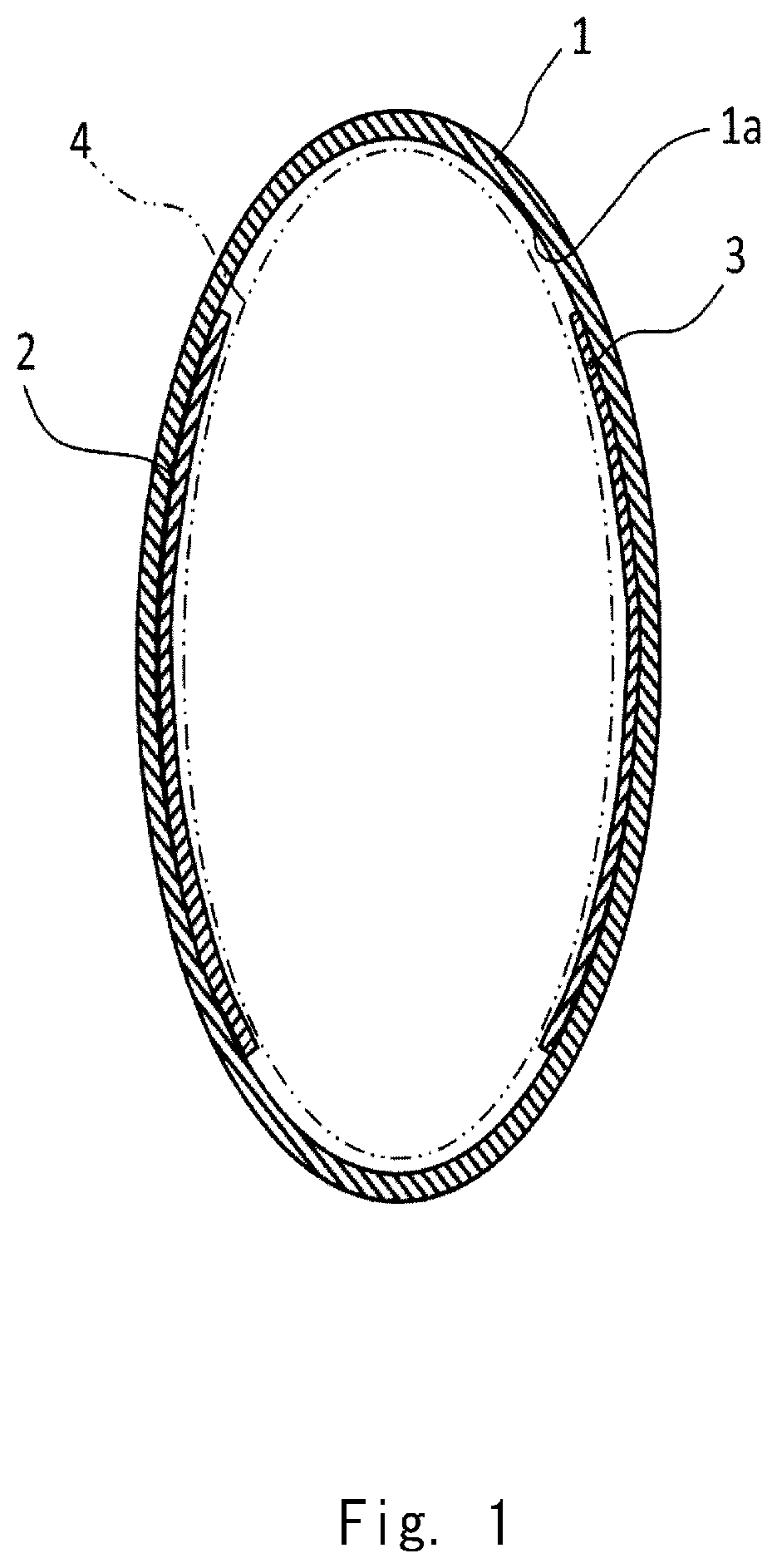
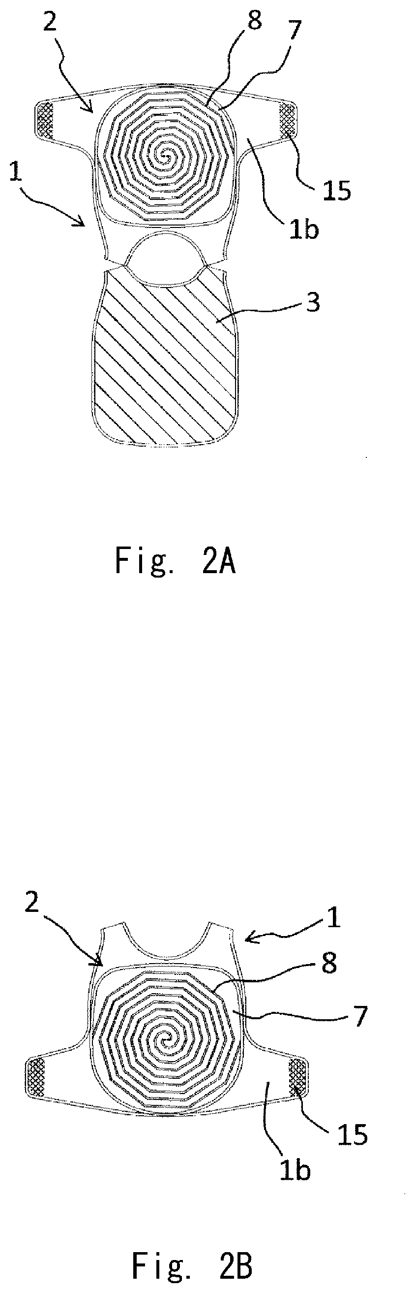
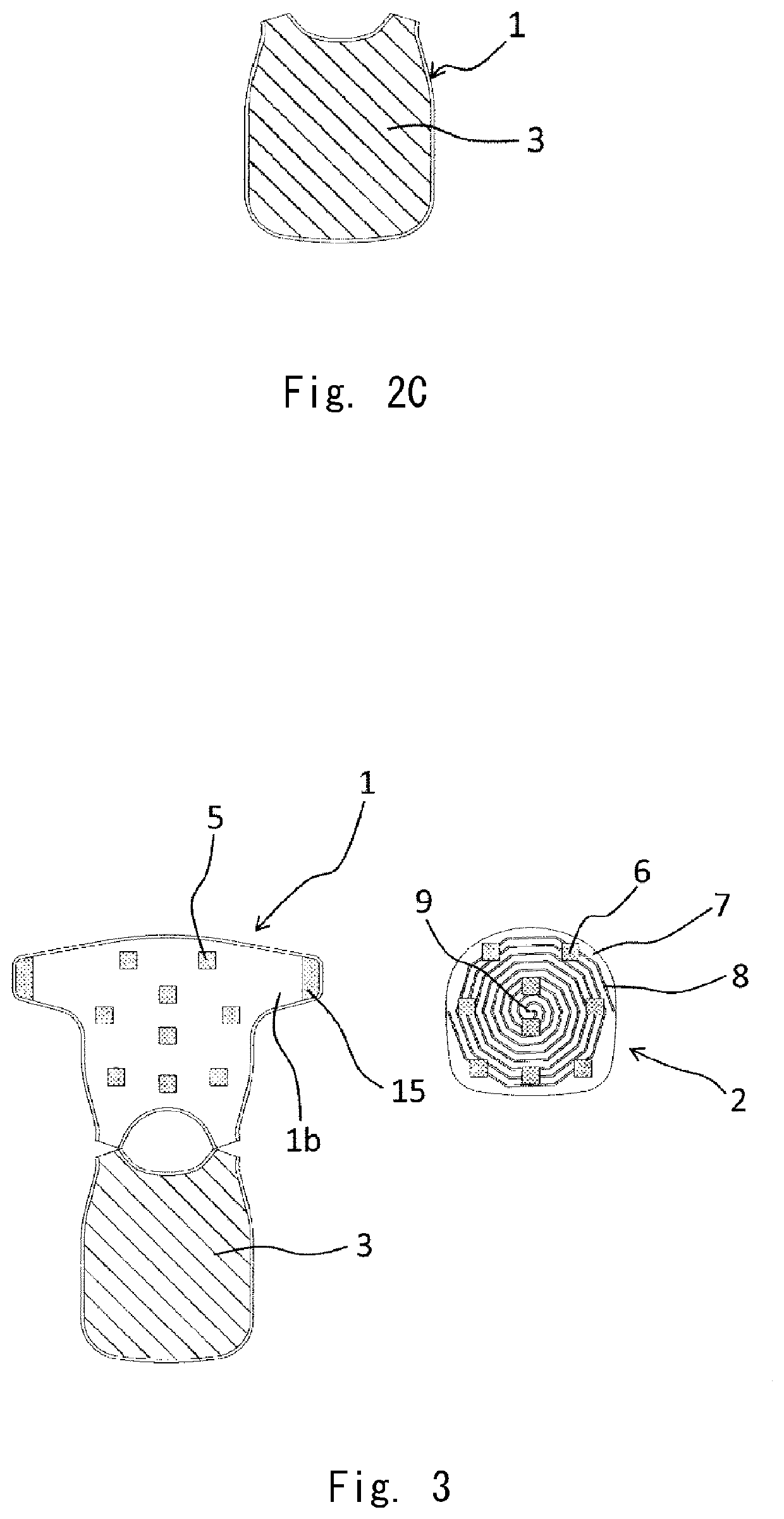
[0035]A wearable antenna device according to a first example embodiment of the present disclosure that is schematically shown in FIG. 1 includes an antenna part 2 and a functional element 3 in a garment 1 including a body accommodation part 1a that accommodates a part of a body 4 (schematically shown in FIG. 1 by an alternate long and two short dashes line). Specifically, the antenna part 2 is arranged in a part of the garment 1, and the functional element 3 is arranged in a position of the garment 1 in such a way that at least a part of the functional element 3 is opposed to the antenna part 2 with the body accommodation part 1a interposed therebetween. Accordingly, at least a part of the antenna part 2 and at least a part of the functional element 3 are opposed to each other via the body accommodation part 1a. While the side of the antenna part 2 with respect to the body accommodation part 1a is referred to as a front side and the direction that is opposite to the antenna part 2 i...

Example

[0051]FIGS. 7A and 7B are diagrams showing a third example embodiment of the wearable antenna device according to the present disclosure. In this example embodiment, the functional element 3 is formed to have a large area, that is, it is formed not only on the rear side (back side) of the vest 1 but also on the front surface of the shoulder part. While the back body part and the front body part of the vest 1 are separated from each other in the exploded view shown in FIG. 7B etc. for the sake of explanation, they are actually formed continuously, and the functional element 3 located on the whole surface of the back body part and the functional element 3 located in the shoulder part of the front body part are continuously formed. According to this structure, the size of the functional element 3 becomes large, and therefore the function thereof is improved. Accordingly, the functional element 3 having a large area contributes to a further improvement in the directivity in the antenna ...

Example

[0052]FIGS. 8A and 8B are diagrams showing a fourth example embodiment of the wearable antenna device according to the present disclosure. In this example embodiment, similar to that in the third example embodiment, the functional element 3 is formed to have a large area, that is, it is formed not only on the rear side (back side) of the vest 1 but also on the front surface of the shoulder part. Further, in this example embodiment, the antenna part 2 is attached to the vest 1 using snap buttons 16 and 17 instead of using surface fasteners 5 and 6. With this structure as well, the antenna part 2 can be easily attached to the vest 1. As shown in a modified example shown in FIG. 8C, in this example embodiment as well, a planar-type antenna element 8 of various forms such as a rectangular spiral antenna can be used.


PUM


Abstract

The wearable antenna device includes an antenna part—attached to a part of a garment including a body accommodation part—that accommodates a part of a body, and a functional element arranged in a position of the garment in such a way that at least a part of the functional element is opposed to the antenna part with the body accommodation part interposed therebetween. The functional element is another antenna part or an element that performs at least one of reflection, shielding, and absorption of radio waves

Description

TECHNICAL FIELD[0001]The present disclosure relates to a wearable antenna device.BACKGROUND ART[0002]In recent years, various types of radio communication services for outdoors such as a mobile telephone, a wireless Local Area Network (LAN), or a Worldwide Interoperability for Microwave Access (WiMAX) have become available. Further, voice transmission using a wireless microphone, a transceiver or the like, and wireless digital image transmission have become widespread, and frequency allocation management based on Radio Act has become important in order to efficiently use limited frequencies.[0003]Further, news media around the world gather for large events such as sports events (Olympics, Paralympics, World Cup of various competitions etc.) and they transmit video data and voice data in real time using various radio communication devices. Therefore, different frequencies are allocated for each the news media around the world. In order to allow the news media of each country to perfo...

Claims


Application Information

Patent Timeline
IPC IPC(8): H01Q1/27H01Q1/52H01Q17/00H01Q15/14H01Q1/36
CPCH01Q15/14H01Q1/526H01Q1/273H01Q17/005H01Q1/36H01Q1/088
Inventor KODAMA, SHINICHIROUKOUNO, KENJISHIMODA, TOMOHIROMUROFUSHI, KAZUAKIMORIYA, HIDENORIKONDO, MITSUNOHIRAKU, SUMIOANDO, YUKIONAGATA, TETSUYA
Owner NEC CORP
Why Eureka
Try Eureka