Wavelength conversion device and light source device

Active Publication Date: 2020-01-23
STANLEY ELECTRIC CO LTD +1
View PDF3 Cites 1 Cited by
  • Summary
  • Abstract
  • Description
  • Claims
  • Application Information

AI Technical Summary

Benefits of technology

[0003]As described above, by arranging optical antennas into an array, the directivity of light emitted from a wavelength conversion element can be improved. However, the illumination device having the antenn

Problems solved by technology

However, the illumination device having the antenna array is susceptible to improvement in terms of reliable emission of the ligh

Method used


Image

  • Wavelength conversion device and light source device
  • Wavelength conversion device and light source device
  • Wavelength conversion device and light source device

Examples


Example

First Embodiment

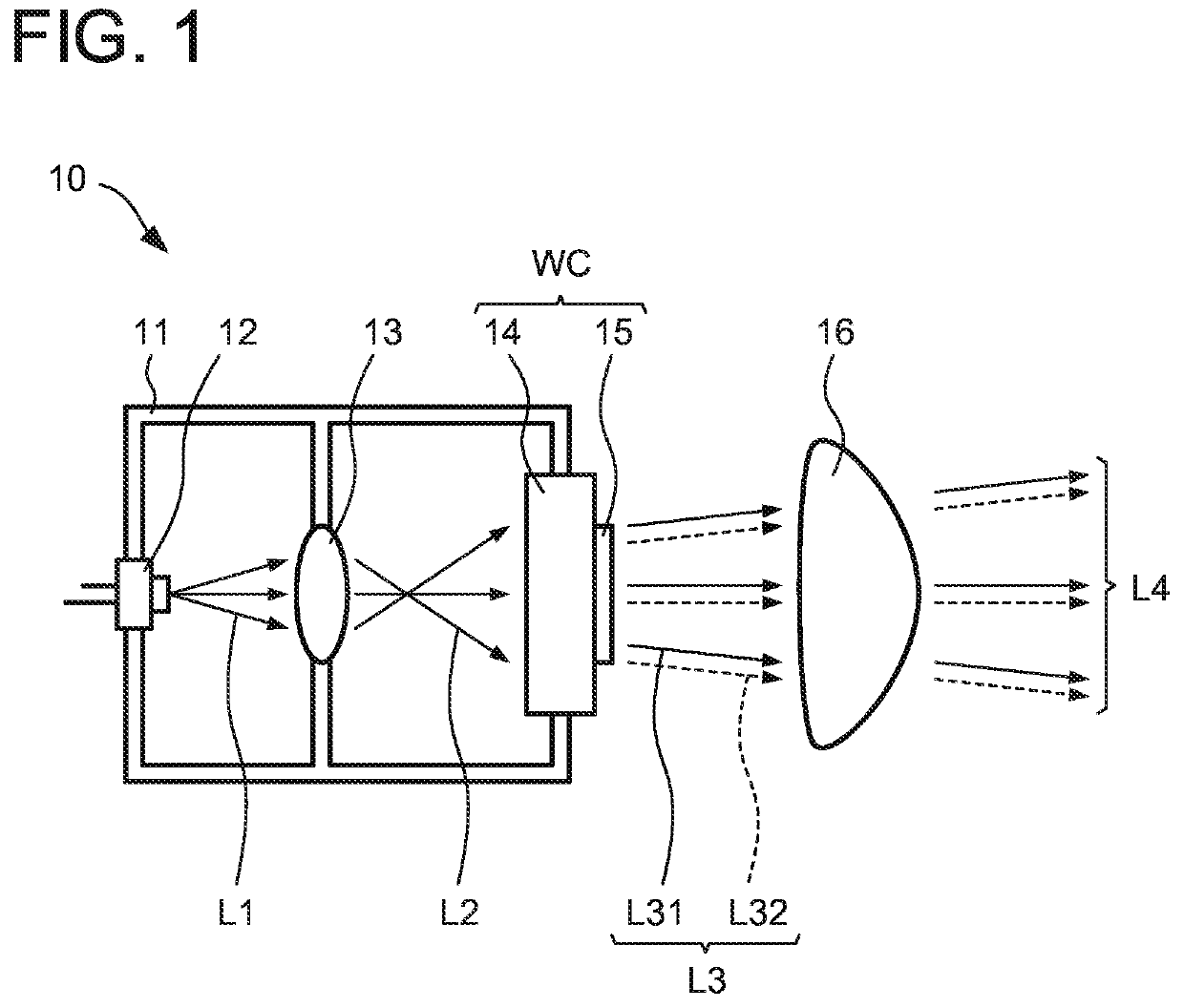
[0022]FIG. 1 is a diagram showing the structure of a light source device 10 according to a first embodiment. FIG. 1 is a schematic cross-sectional view of the light source device 10, though hatching is omitted therein. The light source device 10 includes a light source 12, a shaping optical system 13, a wavelength conversion element 14, and an antenna array 15 contained in a casing 11. The light source device 10 also includes a projection optical system 16 that projects light emitted from the wavelength conversion element 14 and the antenna array 15 to the outside. The light source device 10 can be used as, for example, a lighting device for vehicles and the like.

[0023]The light source 12 emits light of a predetermined wavelength range, as primary light L1. In the present embodiment, the light source 12 includes a laser element that generates a laser beam as the primary light L1, and is a laser source for emitting the laser beam. The light source 12 includes, for exa...

Example

Second Embodiment

[0068]FIG. 5A is a cross-sectional view of a wavelength conversion device WC1 of a light source device 20 according to a second embodiment. FIG. 5B is an enlarged cross-sectional view showing a portion enclosed by broken lines of FIG. 5A, with enlargement. In FIG. 5B, hatching is omitted for the sake of clarity. The wavelength conversion device WC1 will be described with reference to FIGS. 5A and 5B.

[0069]The wavelength conversion device WC1 has the same structure as that of the wavelength conversion device WC except for the structure of a wavelength conversion element 21 and a recessed structure 22. In the wavelength conversion device WC1, the wavelength conversion element 21 has the same structure as that of the wavelength conversion element 14 except for having a phosphor plate 21A having grooves having a V-shaped cross section. The recessed structure 22 has the V-shaped grooves as recessed portions R2.

[0070]More specifically, the recessed portion R2 of the reces...

Example

Third Embodiment

[0084]FIG. 7 is a cross-sectional view of a wavelength conversion device WC3 in a light source device 30 according to a third embodiment. The wavelength conversion device WC3 has the same structure as that of the wavelength conversion device WC except for a phosphor plate 31A and light reflective films 31B. In the wavelength conversion device WC3, the phosphor plate 31A has side surfaces (inclined side surfaces) SS1 that are tapered from a light emission surface S2 toward a light incident surface S1.

[0085]In the present embodiment, the phosphor plate 31A includes side surfaces SS1 that inclinedly extend from the light incident surface S1 pyramidally toward the outside of the phosphor plate 31A, and side surfaces SS2 that extend from the side surfaces SS1 orthogonally to the light incident surface S1.

[0086]Since the phosphor plate 31A has the side surfaces SS1, a part of light that is present in the phosphor plate 31A and is repeatedly reflected between the side surfa...


PUM


Abstract

A wavelength conversion device includes: a wavelength conversion element having a phosphor plate that converts the wavelength of incident light upon a light incident surface to generate wavelength-converted light, and emits the wavelength-converted light from a light emission surface; an antenna array constituted of a plurality of optical antennas that are periodically arranged on the light emission surface of the phosphor plate; and a recessed structure including at least one recessed portion provided in the light emission surface of the phosphor plate.

Description

BACKGROUND OF THE INVENTION1. Field of the Invention[0001]The present invention relates to a wavelength conversion device for converting the wavelength of light, and a light source device including the wavelength conversion device.2. Background Art[0002]Conventionally, light source devices that combine a light source that emits light of a predetermined wavelength (emission color) and a wavelength conversion device that converts the wavelength of the light from the light source and outputs the converted light are known. For example, Japanese Patent Application Laid-Open No. 2018-13688 discloses an illumination device that includes a light source, a wavelength conversion element, and an antenna array, as a light source device having improved directivity of emission light.SUMMARY OF THE INVENTION[0003]As described above, by arranging optical antennas into an array, the directivity of light emitted from a wavelength conversion element can be improved. However, the illumination device ha...

Claims


Application Information

Patent Timeline
IPC IPC(8): F21K9/64F21K9/65F21K9/68
CPCF21Y2115/30F21K9/68F21K9/64F21K9/65F21V9/32H01L33/507G03B21/204H01L33/50F21Y2115/10G02B5/008G02B1/005H01S5/02H01S5/32341H01S5/0087H01S5/02257
Inventor MURAI, SHUNSUKEYOKOBAYASHI, YUSUKEKAWAKAMI, YASUYUKITAKASHIMA, KEIJIROKUBO, SYOUSAKUMAEMURA, YOSUKE
Owner STANLEY ELECTRIC CO LTD
Why Eureka
Try Eureka