Broadband antenna

a broadband antenna and antenna technology, applied in the direction of rhombic antennas, resonant antennas, non-resonant long antennas, etc., can solve the problems of not being suitable for mobile communication terminals such as mobile phones, not being suitable for mobile communication terminals, and not being small, so as to achieve the effect of being ready to be miniaturized

Inactive Publication Date: 2008-03-06
SAMSUNG ELECTRO MECHANICS CO LTD
View PDF8 Cites 4 Cited by
  • Summary
  • Abstract
  • Description
  • Claims
  • Application Information

AI Technical Summary

Benefits of technology

[0009]An aspect of the present invention provides an antenna readily mini

Problems solved by technology

However, a VHF antenna of a low frequency range (e.g. hundreds of MHz band), in particular, an antenna for ground wave DMB requires tens of centimeters of length for ensuring a resonant frequency, and thus is not suitable to be mounted in the mobile communication terminal.
The broadband antennas currently under development includ

Method used


Image

  • Broadband antenna
  • Broadband antenna
  • Broadband antenna

Examples


Embodiment Construction

[0035]Exemplary embodiments of the present invention will now be described in detail with reference to the accompanying drawings.

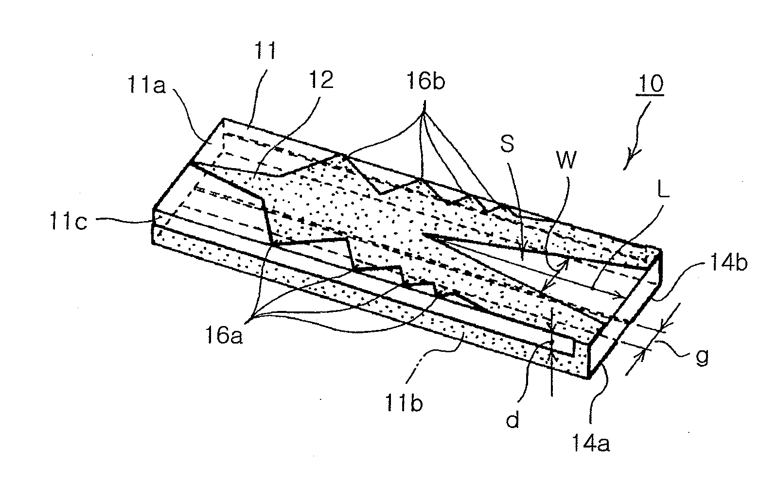
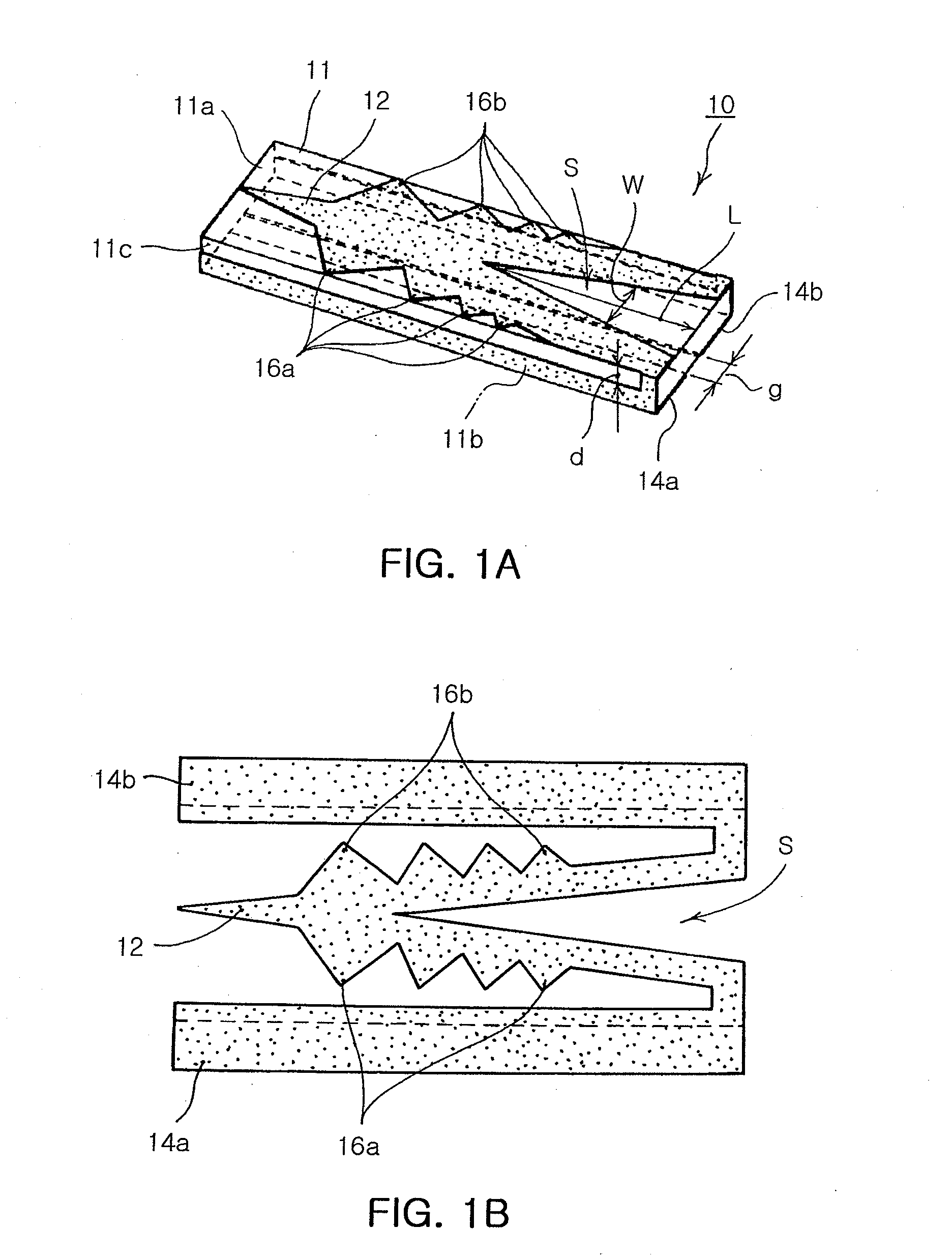
[0036]FIG. 1A is a perspective diagram illustrating a broadband antenna according to an exemplary embodiment of the present invention and FIG. 1B is a development diagram illustrating the radiator pattern of the broadband antenna shown in FIG. 1A.

[0037]As shown in FIGS. 1A and 1B, the broadband antenna 10 includes first and second main surfaces 11a and 11b opposing each other; an insulating block 11 having a side surface 11c between the first and second main surfaces; and first and second radiator patterns 12, 14a and 14b formed on the first and second main surfaces 11a and 11b, respectively.

[0038]In this embodiment, the first radiator pattern 12 and the second radiator pattern 14a and 14b are connected to each other to substantially work as one radiator pattern. As shown, the first and second radiator patterns 12, 14a and 14b may have a symmetric structur...


PUM


Abstract

There is provided a broadband antenna including: an insulating block having opposing first and second main surfaces and a side surface between the first and second main surfaces; a first radiator pattern formed on the first main surface and having a tapered slot with an open end; and a second radiator pattern including two patterns connected to opposing ends of the first radiator pattern, respectively, and extending to the second main surface.

Description

CLAIM OF PRIORITY[0001]This application claims the benefit of Korean Patent Application No. 2006-0083106 filed on Aug. 30, 2006, in the Korean Intellectual Property Office, the disclosure of which is incorporated herein by reference.BACKGROUND OF THE INVENTION[0002]1. Field of the Invention[0003]The present invention relates to a broadband antenna, and more particularly, to an antenna having broadband characteristics in a low frequency band.[0004]2. Description of the Related Art[0005]Recently, mobile communication terminals are diversified in the frequency ranges with advancement in wireless communication technology. In particular, the frequency bands currently used in the wireless communication include: 800 MHz to 2 GHz for global system for mobile communication (GSM) and code division multiple access (CDMA) mobile phones; 2.4 GHz and 5 GHz for wireless local area network (WLAN); 13.56 MHz, 433.92 MHz, 908 to 914 MHz, 2.45 GHz for non-contact radio frequency identification (RFID);...

Claims


Application Information

Patent Timeline
IPC IPC(8): H01Q11/06H01Q1/00H01Q11/10
CPCH01Q1/38H01Q9/40H01Q9/44H01Q1/243H01Q5/50
Inventor BAE, SEOKKIM, IN YOUNG
Owner SAMSUNG ELECTRO MECHANICS CO LTD
Why Eureka
Try Eureka