
Gloss providing sheet and image formation apparatus

a technology of providing sheet and providing sheet, which is applied in the direction of electrographic process apparatus, instruments, developers, etc., can solve the problems of deformation of surface shape, inability to provide smooth high-gloss image, and difficulty in forming uniform high-gloss image as created by silver halide photography

Inactive Publication Date: 2008-03-06
RICOH KK
View PDF3 Cites 14 Cited by
  • Summary
  • Abstract
  • Description
  • Claims
  • Application Information

AI Technical Summary

Benefits of technology

The present invention provides an improved and useful gloss-providing sheet for providing high gloss to a toner image on a recording material. The gloss-providing sheet is placed on the toner image surface of the recording material, heated so as to fuse toner, and then separated from the recording material. The gloss-providing sheet has a notification portion that changes color when the temperature of the gloss-providing sheet becomes equal to or lower than the glass transition temperature of the toner. The notification portion may be in the entire sheet or a portion of the sheet. The gloss-providing sheet helps to confirm that the toner is sufficiently cooled and solidified before separation from the recording material. The invention also provides an image formation apparatus for forming a toner image on a recording material using the gloss-providing sheet.

Problems solved by technology

In an image formation apparatus employing electrophotography, it has been difficult to form a uniform high-gloss image as created by silver halide photography.
However, when the toner is sufficiently fused, a fixing method using a conventional fixing roller and a fixing belt poses problems such as hot offset where the toner is adhered to the fixing roller and winding where the recording material is wound around the fixing roller.
Further, there is another problem in that while the toner is fused at high temperature, when a toner surface is separated from the fixing roller or the fixing belt, a surface shape is deformed and a smooth high-gloss image is not provided.
However, on a halftone made of dots or lines, it is impossible to form a uniform high-gloss image since fields where the toner is placed and where the toner is not placed are mixed and convexity and concavity are inevitably formed on the surface.
However, these apparatuses have little practical use since any of such apparatuses requires a large-scale device and some users do not prefer laminated images, so that such apparatuses have been hardly used.
In an image formation apparatus employing electrophotography, it has been difficult to form a uniform high-gloss image as created by silver halide photography largely because toner having a particle size of not less than 5 μm is used when attempting to have a smooth surface for an image.
However, on a halftone made of dots or lines, it is impossible to form uniformly high-gloss since fields where the toner is placed and where the toner is not placed are mixed and convexity and concavity are inevitably formed on the surface.
However, even when this recording material is used, a fixing method for a conventional fixing device using a fixing roller and a fixing belt poses problems such as hot offset where the toner is adhered to the fixing roller when the toner is sufficiently fused and winding where the recording material is wound around the fixing roller.
Further, there is another problem in that while the toner is fused at high temperature, when a toner surface is separated from the fixing roller or the fixing belt, a surface shape is deformed and a smooth high-gloss image is not provided.
However, this method requires a large-scale device, so that there are problems in terms of cost and size.
However, these apparatuses have little practical use since any of such apparatuses requires a large-scale device and some users do not prefer laminated images, so that such apparatuses have been hardly used.
However, the fixing device has problems in that cost is increased, print speed cannot become fast because of the necessity of cooling time, and the belt has life resulting from degradation of the gloss surface of the belt because a structure of the device is different from that of a conventional fixing device.
However, when the gloss-providing sheet is separated, if the user erroneously separates the sheet while the toner is not sufficiently cooled and solidified, a smooth surface of the toner is deformed and a uniform high-gloss image is not obtained.

Method used


Image

  • Gloss providing sheet and image formation apparatus
  • Gloss providing sheet and image formation apparatus
  • Gloss providing sheet and image formation apparatus

Examples


Embodiment Construction

[0072] In the following, embodiments of the present invention will be described with reference to the accompanying drawings.

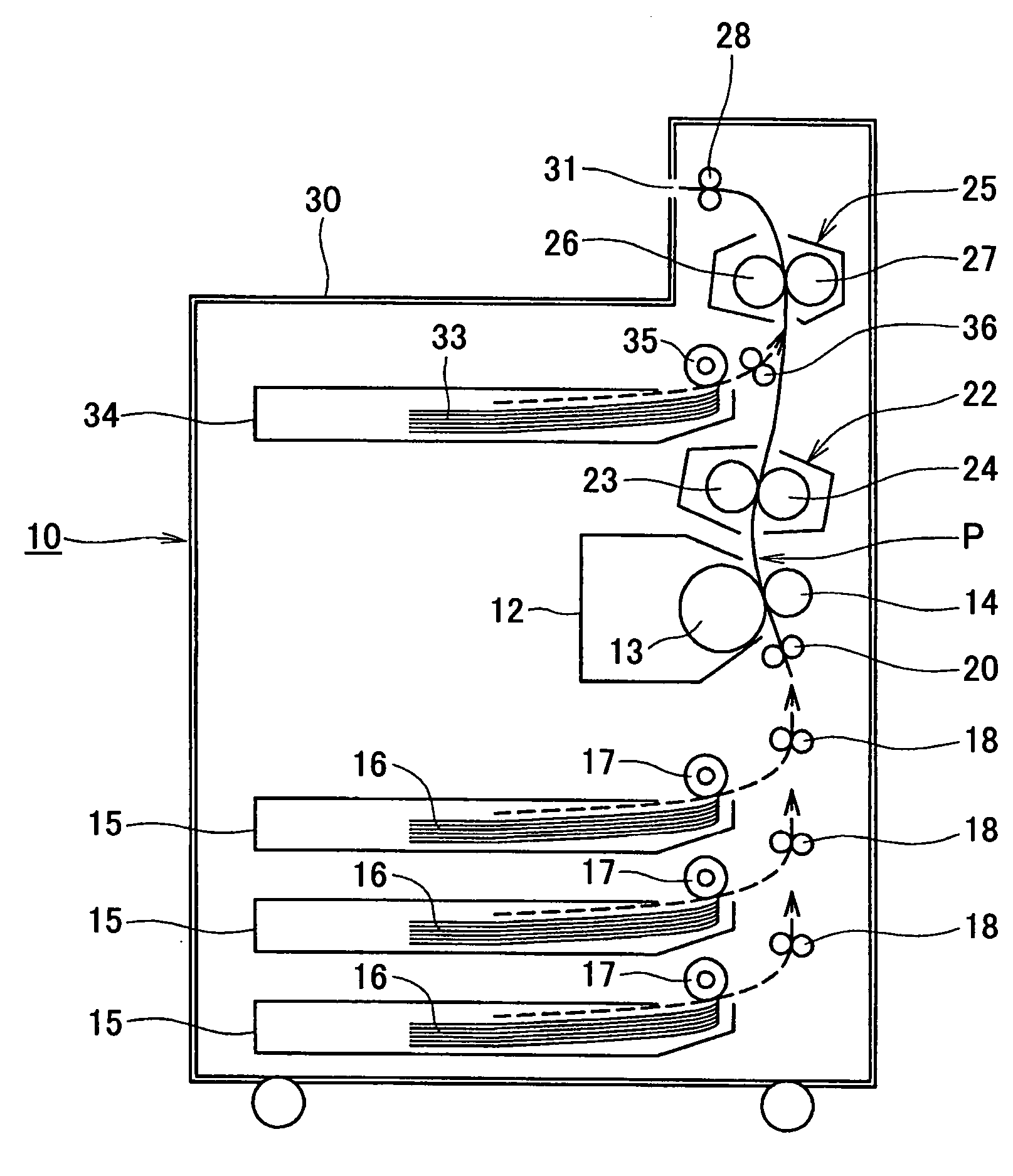
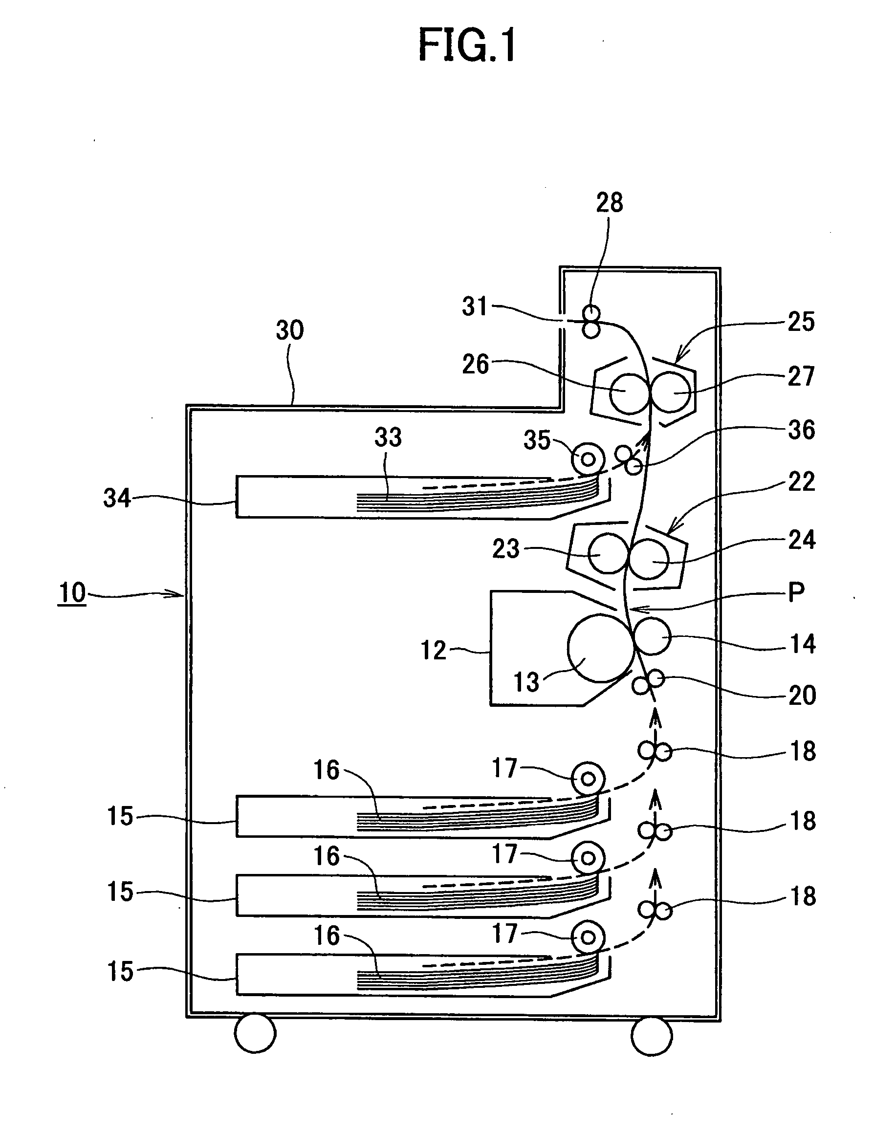
[0073]FIG. 1 is a schematic configuration diagram showing an entire portion of an electrophotographic image formation apparatus using a gloss-providing sheet according to the present invention.

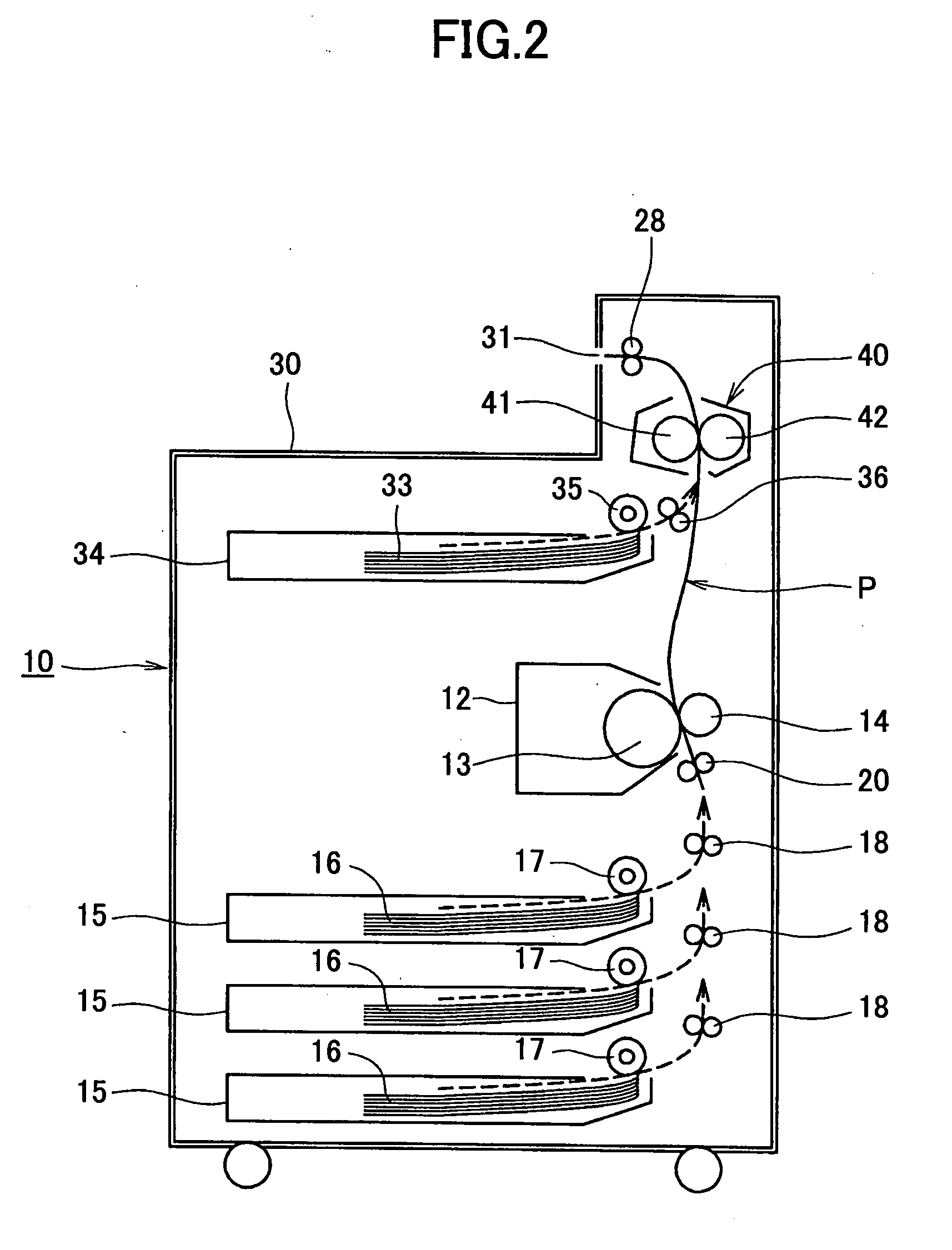
[0074] An image formation apparatus body referenced at 10 includes a process unit 12 detachably disposed on a middle portion. A photoconductor 13 having a drum-like shape is rotatably disposed on the process unit 12 and a charging unit, development unit, and the like (not shown in the drawings) are disposed on a periphery of the photoconductor 13. Further, in the vicinity of the process unit 12, a writing unit (not shown in the drawings) is disposed. A transfer device 14 having a roller shape is pressed on the photoconductor 13 of the process unit 12, the transfer device 14 being disposed so as to face the photoconductor 13 across a recording material conveying path P, ...


PUM


Abstract

A disclosed gloss-providing sheet for providing high gloss to a toner image on a recording material by being placed on a toner image surface of the recording material, heated so as to fuse toner, and then separated from the recording material after the toner is cooled and solidified includes: a notification portion that changes a visual state thereof when a temperature of the gloss-providing sheet becomes equal to or lower than a glass transition temperature of the toner.

Description

BACKGROUND OF THE INVENTION [0001] 1. Field of the Invention [0002] The present invention relates to a gloss-providing sheet for providing high gloss to a toner image on a recording material in which the gloss-providing sheet is placed on a toner image surface of the recording material such as paper and is heated so as to fuse toner, and then the gloss-providing sheet is separated from the recording material after the toner is cooled and solidified. Further, the present invention relates an image formation apparatus such as a copying machine, printer, facsimile machine, multi-function device thereof, and the like using such a gloss-providing sheet and more particularly to an image formation apparatus employing electrophotography. [0003] 2. Description of the Related Art [0004] In an image formation apparatus employing electrophotography, it has been difficult to form a uniform high-gloss image as created by silver halide photography. The high-gloss image has a smooth surface and it ...

Claims


Application Information

Patent Timeline
Patent Type & Authority Applications(United States)
IPC IPC(8): G03G15/20G03G11/00
CPCG03G8/00G03G11/00G03G15/2021G03G15/6582G03G2215/00805G03G15/2064
Inventor MARUYAMA, HITOSHIYASUTOMI, KEIMURAKAMI, EISAKUNAKAMURA, REKI
Owner RICOH KK
Learn More