Outdoor umbrella with ventilation arrangement

a technology of ventilation arrangement and outdoor umbrella, which is applied in the field of umbrellas, can solve the problems of few, if not no, comprehensive outdoor umbrellas capable of providing electrical appliances, and great trouble, and achieves the effect of reducing the risk of injury

Inactive Publication Date: 2008-03-06
LI WANDA YING
View PDF4 Cites 30 Cited by
  • Summary
  • Abstract
  • Description
  • Claims
  • Application Information

AI Technical Summary

Benefits of technology

[0010]A main purpose of the present invention is to provide an outdoor umbrella which comprises a ventilation arrangement which is capable of creating airflow under awning arms for providing a ventilating effect as an additional function for the outdoor umbrella.

Problems solved by technology

For instances, they require light during night time and they may need fans when the weather is too hot.
As a result, they may bring their own light and fans to the intended activities and this may create great trouble to them.
Therefore, this is the main disadvantage to conventional outdoor umbrella I in that a typical outdoor activity usually requires a wide range of electrical appliances, such as lighting devices, audio devices, or ventilating devices for providing extra support to the activities being held.
However due to power availability, mounting limitation and ease of control, there are currently very few, if not no, comprehensive outdoor umbrella which is capable of providing electrical appliances other than lighting devices.
Another problem, however, may exist.
Since the outdoors umbrellas have to support many electrical appliances with proper electrical connection, it becomes more difficult for the usual folding or unfolding mechanisms to operate.
In short, the electrical appliances may actually affect the operation of the outdoor umbrellas so as to defeat the very purpose of having those outdoor umbrellas.

Method used


Image

  • Outdoor umbrella with ventilation arrangement
  • Outdoor umbrella with ventilation arrangement
  • Outdoor umbrella with ventilation arrangement

Examples


Embodiment Construction

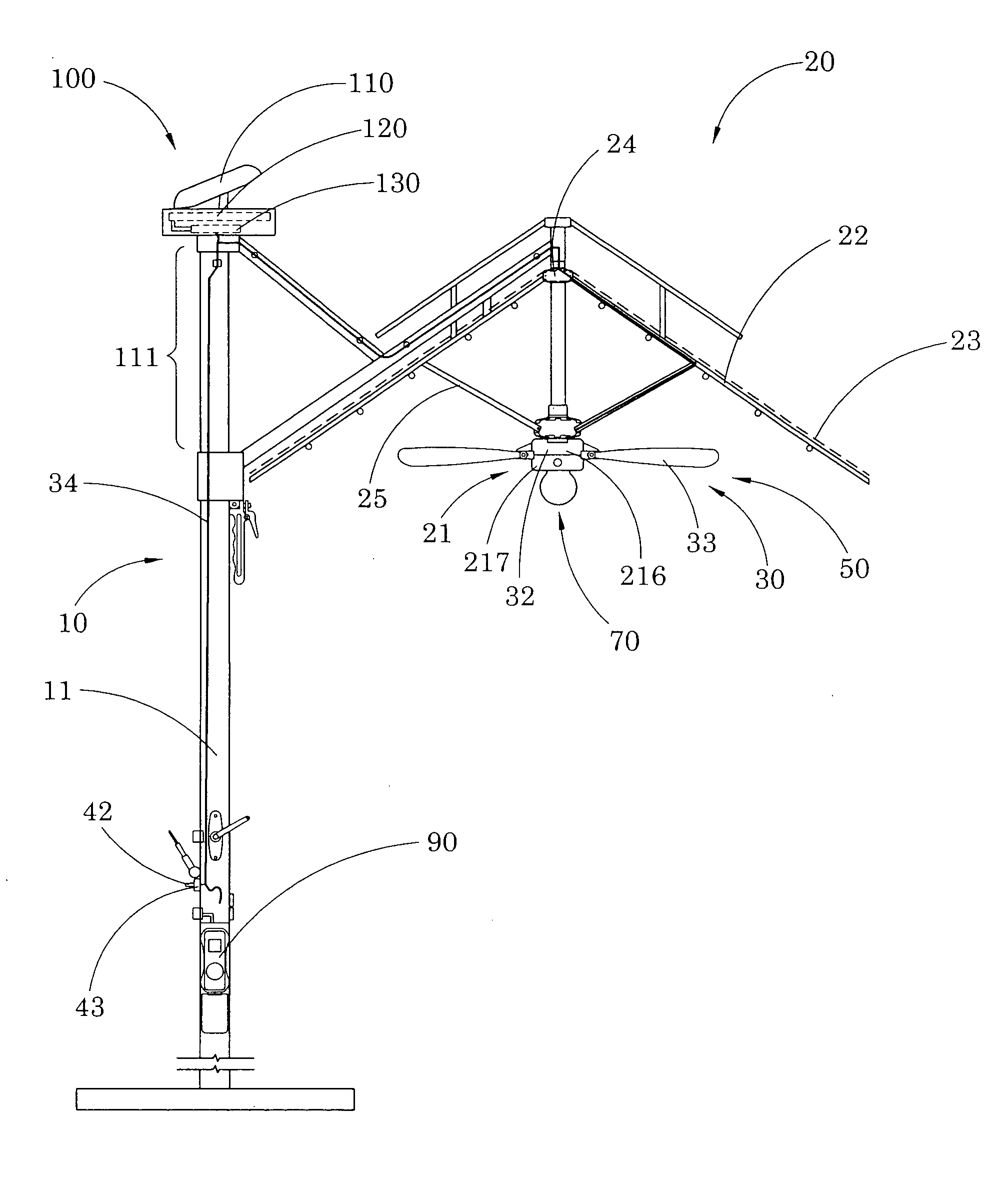
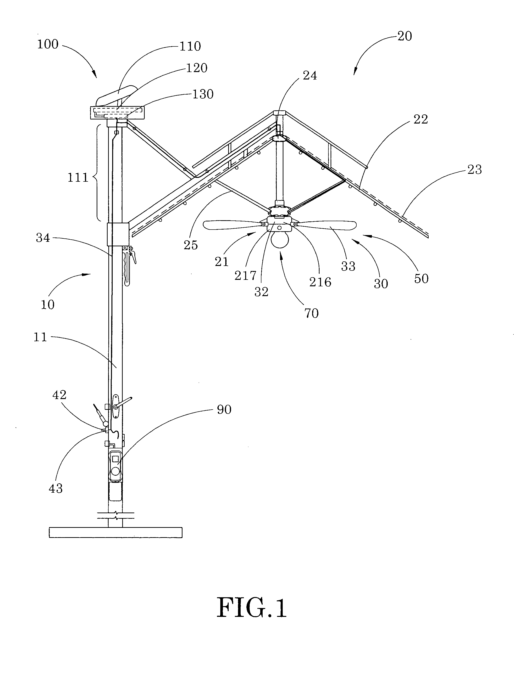
[0032]Referring to FIG. 1 to FIG. 4, and FIG. 6 and FIG. 7 of the drawings, an outdoor umbrella according to a preferred embodiment of the present invention is illustrated, in which the outdoor umbrella comprises a supporting frame 10, an awning frame 20, a ventilation arrangement 30, and a connector head 60.

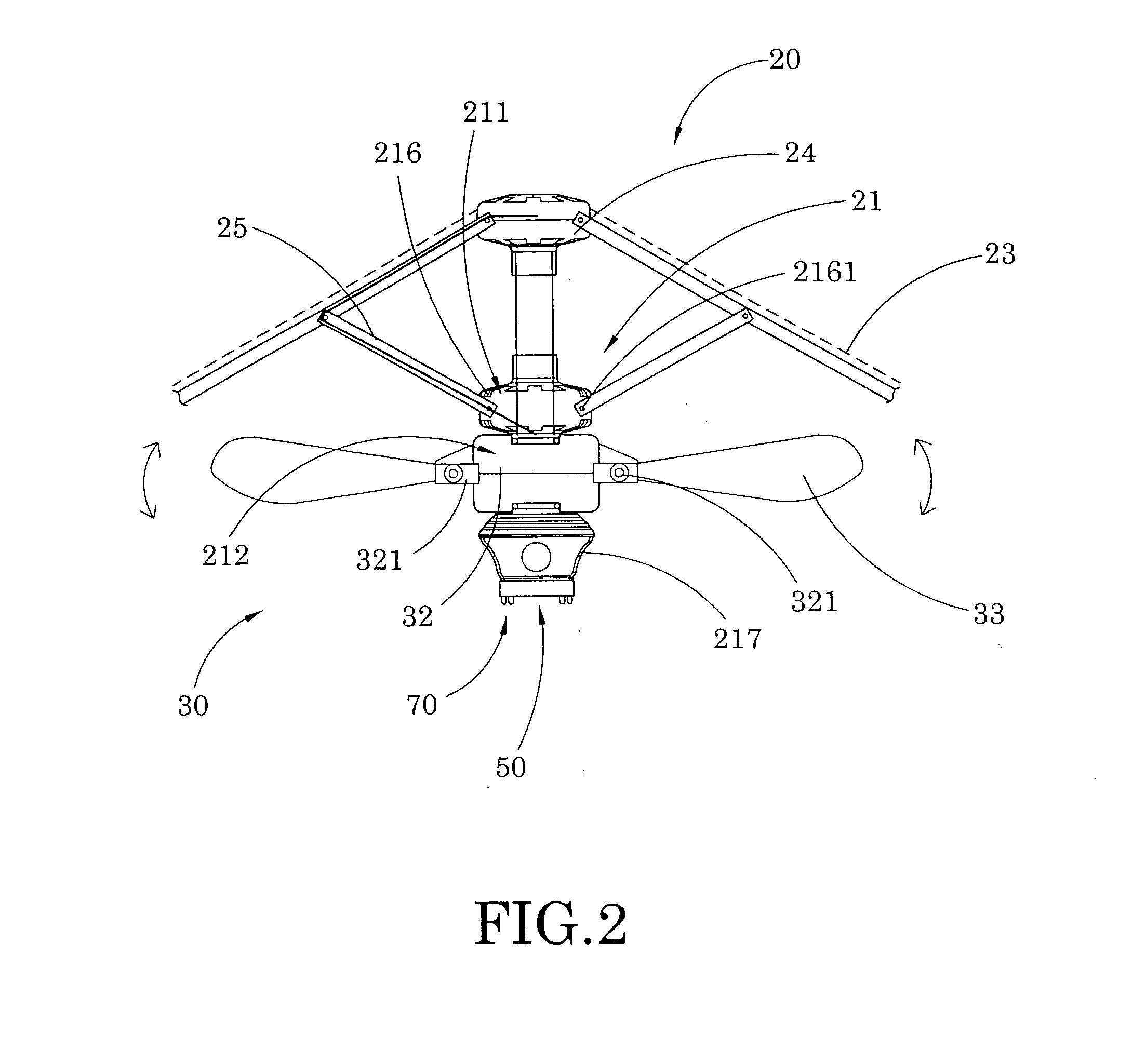
[0033]The awning frame 20 comprises a functional umbrella hub 21 suspendedly supported by the supporting frame 10, a plurality of awning arms 22 radially and outwardly extended from the functional umbrella hub 21, and an awning 23 supported by the awning arms 22 to define a shading area under the awning 23.

[0034]The functional umbrella hub 21 further comprises a functional appliance for electrically connecting with the connector head 60, wherein the functional appliance comprises is embodied as a wide range of electrical appliances adapted for being installed onto the outdoor umbrella, such as the ventilation arrangement 30.

[0035]The ventilation arrangement 30 comprises a ventil...


PUM


Abstract

An outdoor umbrella includes a supporting frame, an awning frame and a ventilation arrangement. The awning frame includes a functional umbrella hub suspendedly supported by the supporting frame, a plurality of awning frames radially and outwardly extended from the functional umbrella hub, and an awning supported by the awning arms to define a shading area under the awning. The ventilation arrangement includes a ventilation power unit, a driving rotor, and a plurality of fan blades. The fan blades are spacedly mounted to the driving rotor such that when the driving rotor is driven to rotate, the fan blades are swinging for creating an airflow under the awning arms within the shading area, so as to provide a ventilating effect as an additional function for the outdoor umbrella.

Description

BACKGROUND OF THE PRESENT INVENTION[0001]1. Field Of Invention[0002]The present invention relates to an umbrella, and more particularly to an outdoor umbrella comprising a ventilation arrangement which is capable of creating airflow under awning arms for providing a ventilating effect as an additional function for the outdoor umbrella.[0003]2. Description of Related Arts[0004]A conventional outdoor umbrella usually comprises a supporting frame, an awing frame movably supported on the supporting frame, and an awning fabric supported on the awning frame for proving shading in a shading area under the awing fabric.[0005]Conventionally, the outdoor umbrella is usually foldable so that when it is not in use, the outdoor umbrella can be folded into a compact size for convenient transport and storage.[0006]People usually use the conventional outdoor umbrella for a wide variety of outdoor activities. For example, people may use the outdoor umbrella during camping for providing some sort of ...

Claims


Application Information

Patent Timeline
Patent Type & Authority Applications(United States)
IPC IPC(8): B64C11/28
CPCA45B3/00A45B3/02A45B2200/1036A45B2023/0012A45B2023/0037A45B23/00
Inventor LI, WANDA YING
Owner LI WANDA YING
Why Eureka
Try Eureka