Air current generator

a generator and air current technology, applied in space heating and ventilation, lighting and heating apparatus, heating types, etc., can solve the problems of significant energy loss when electrical energy is converted into mechanical energy, too noisy air conditioning system, and inconvenient use of domestic use, etc., to achieve enhanced structural design flexibility, wide range of applications, and facilitate wide range of applications

Inactive Publication Date: 2007-06-21
ZHIXIANG SU
View PDF4 Cites 8 Cited by
  • Summary
  • Abstract
  • Description
  • Claims
  • Application Information

AI Technical Summary

Benefits of technology

[0011] Another object of the present invention is to provide an air current generator which may be embodied as a wide range of air delivering or purifying devices so as to facilitate a wide range of applications of the present invention.
[0012] Another object of the present invention is to provide an air current generator which is capable of generating airflow having a flow rate comparable with most conventional air ventilating device, so that the present invention can be utilized in lieu of conventional air ventilating devices, with the advantages of enhanced flexibility in structural design and having a wider range of applications.
[0013] Another object of the present invention is to provide an air current generator which is capable of creating airflow for air conditioning purpose without simultaneously generating significant noise.
[0014] Another object of the present invention is to provide an air current generator which does not involve complicated mechanical or electrical components so as to minimize the manufacturing cost as well as the ultimate selling price of the present invention.

Problems solved by technology

There are several disadvantages with this kind of convention airflow generator.
First and foremost, the airflow generator, such as the axial fan, is responsible for generating a high level of noise so as to severely undermine the range of applications of the entire air ventilating device.
For example, too noisy an air conditioning system is not suitable for domestic use because the noise may affect family members to have a good sleep.
Secondly, since the airflow generator is operated by rotation of a plurality of fan blades, there is significant energy loss when electrical energy is transformed to mechanical energy.
As a result, there is little flexibility in terms of its use and design.
Finally, it is important to note that the above-mentioned disadvantages also apply to a conventional heating system.

Method used


Image

  • Air current generator
  • Air current generator
  • Air current generator

Examples


Embodiment Construction

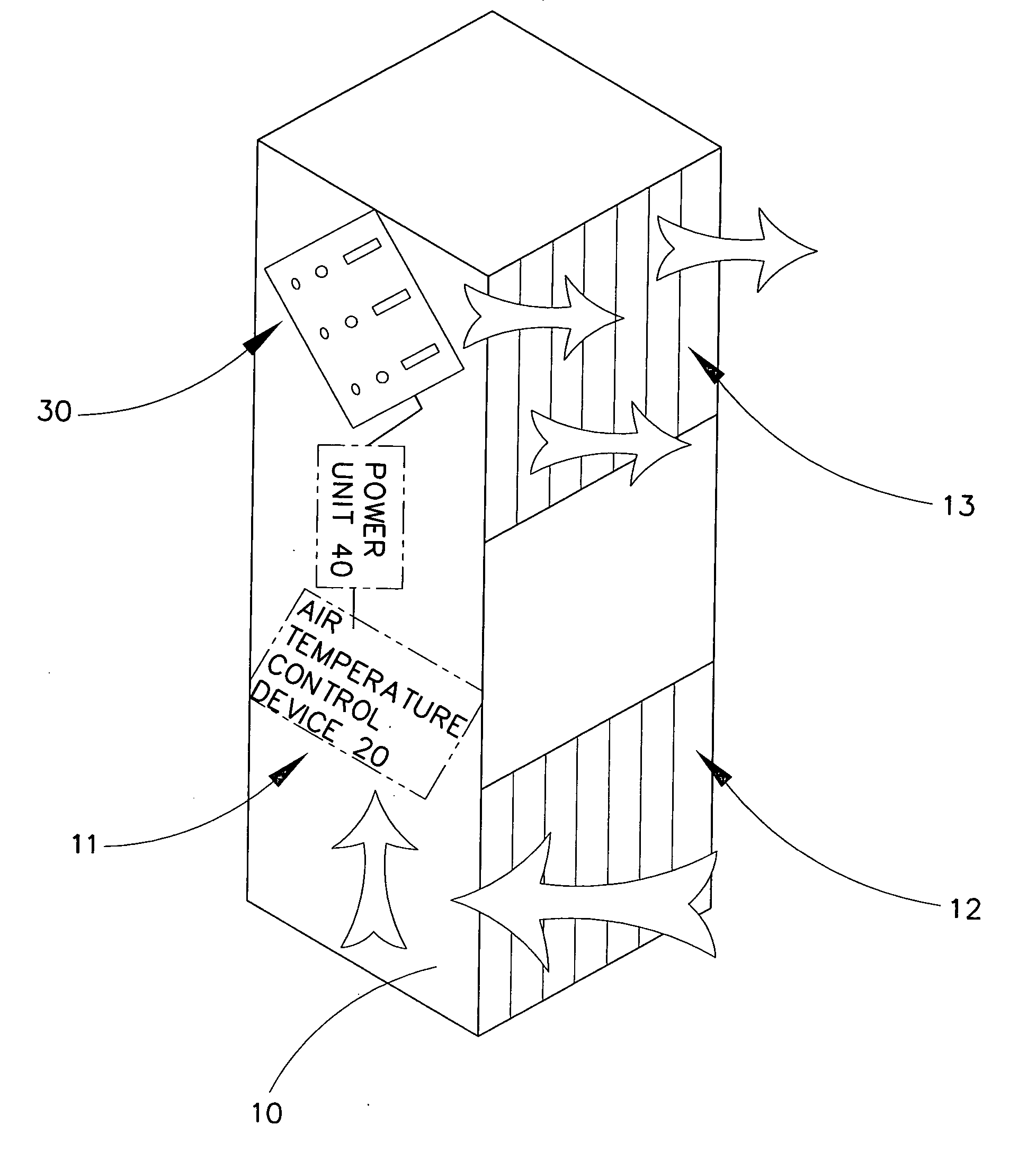
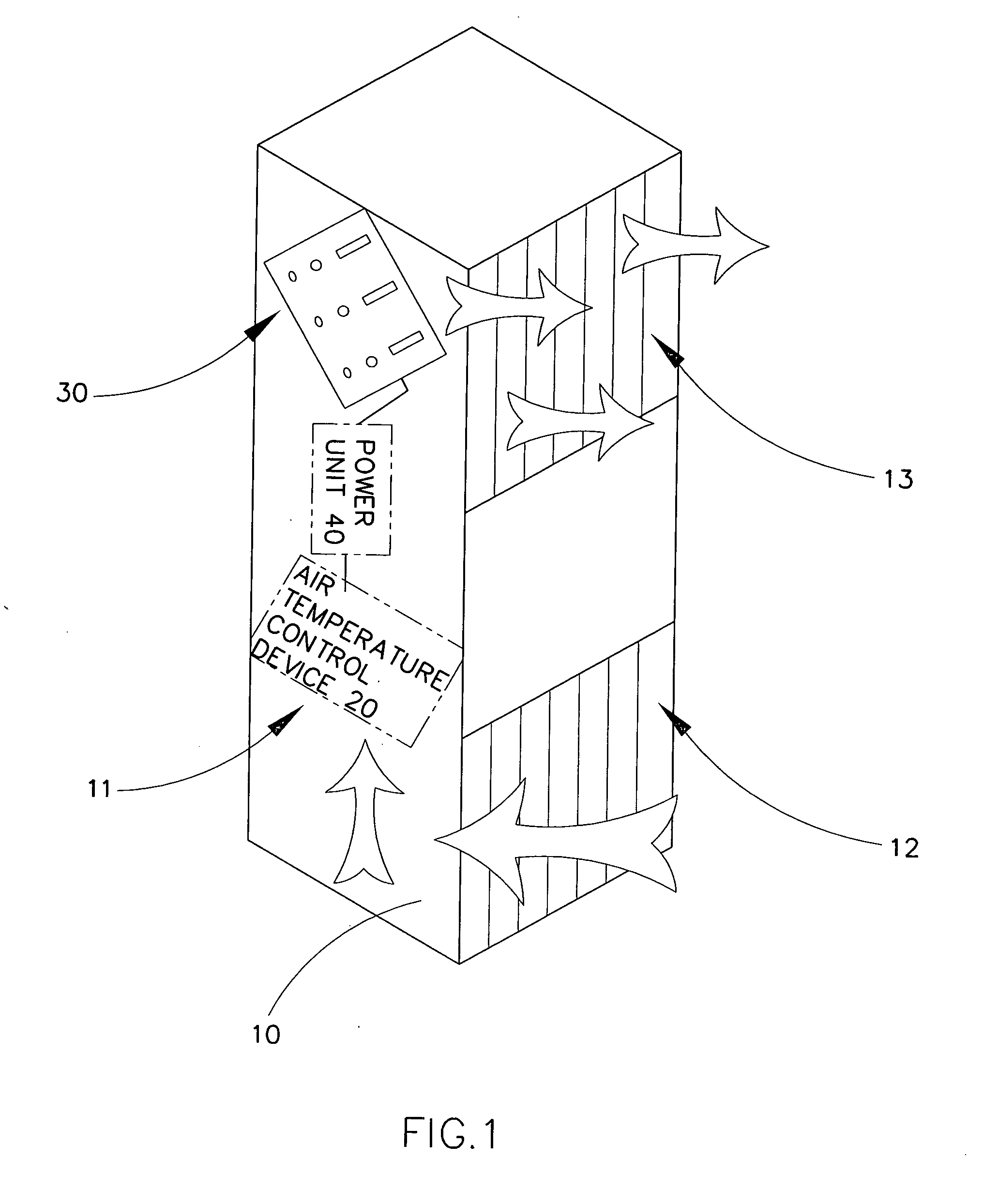
[0032] Referring to FIG. 1 to FIG. 2, FIG. 3A and FIG. 3B of the drawings, an air current generator according to a preferred embodiment of the present invention is illustrated, in which the air current generator comprises an outer casing 10, an air temperature control device 20, an ionizing airflow generator 30, and a power unit 40 supported within the outer casing 10.

[0033] The outer casing 10 has an air ventilating cavity 11, an air inlet 12 and an air outlet 13 communicating the air ventilating cavity 11 with an exterior of the outer casing 10.

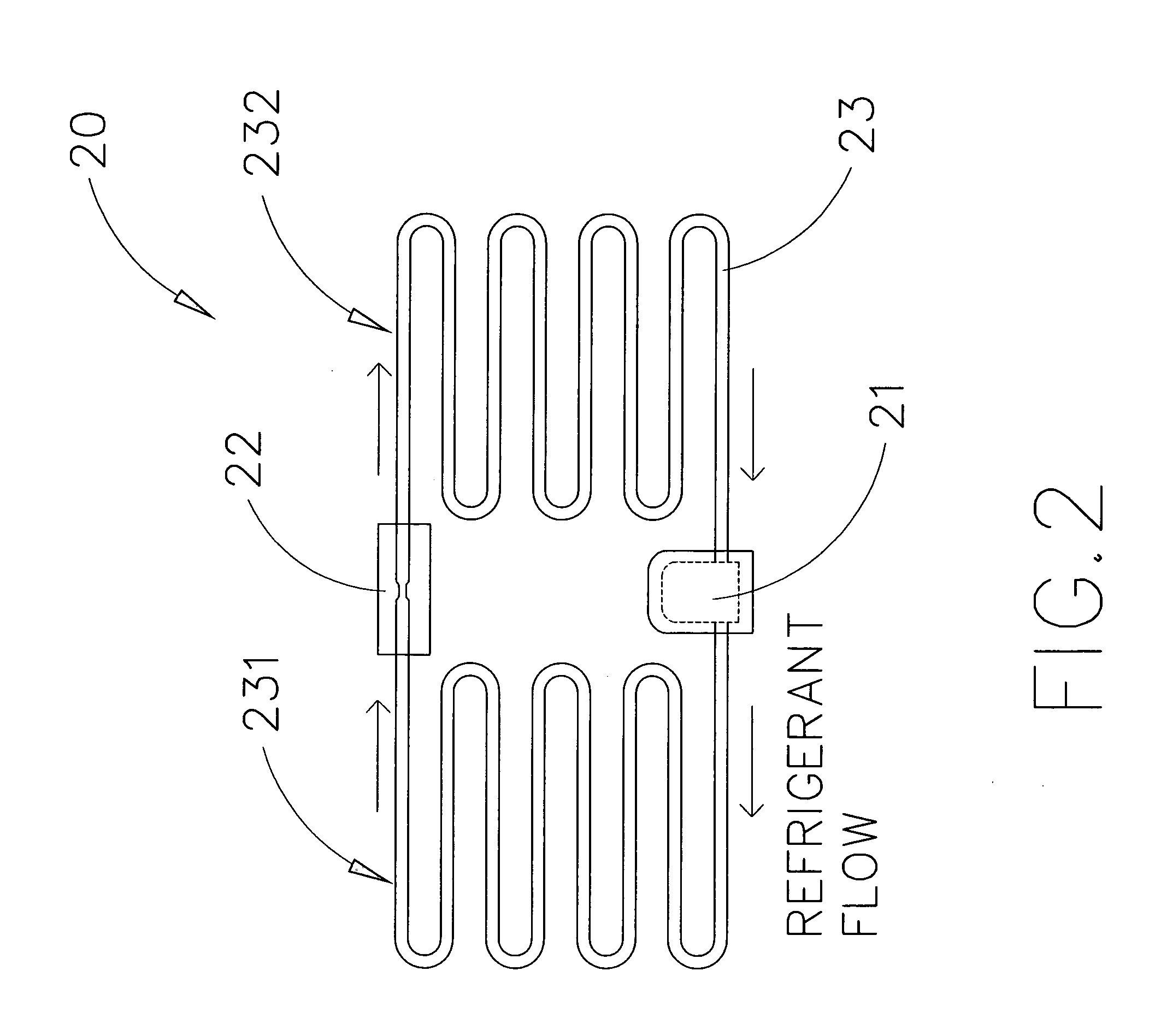
[0034] The air temperature control device 20, such as an air cooling device, is electrically connected to the power unit 40 for generating a temperature-controlled air within the air ventilating cavity 11 of the outer casing 10.

[0035] The ionizing airflow generator 30 is electrically connected to the power unit 40, and comprises an ionizing airflow unit 31, which is electrically connected to the power unit 40, and comprises a first elect...


PUM


Abstract

An air current generator includes an outer casing, a power unit, an air temperature control device, and an ionizing airflow generator. The air temperature control device is electrically connected to the power unit for generating a temperature-controlled air within the air ventilating cavity of the outer casing. The ionizing airflow generator includes an ionizing airflow unit which includes a first electrode set as an electrode terminal disposed within the outer casing at a position close to an air inlet, and a second electrode set disposed within the outer casing at an air outlet, wherein a voltage of the second electrode set is higher than a voltage of the first electrode set to generate an electrostatic force for drawing a flow of air from the air inlet to the air outlet so as to guide the temperature-controlled air within the outer casing to the exterior of the outer casing through the air outlet.

Description

BACKGROUND OF THE PRESENT INVENTION [0001] 1. Field of Invention [0002] The present invention relates to an air delivering device, and more particularly to an air current generator which comprises an ionizing airflow generator for producing air flow so as to deliver cool or heated air to an exterior of the air current generator. [0003] 2. Description of Related Arts [0004] A conventional air ventilating device, such as a conventional air conditioning device, usually comprises an outer casing having an air inlet and an air outlet, a heat exchanging system provided in the outer casing, and an airflow generator mounted within the outer casing to operatively communicate with the heat exchanging system, in such a manner that the airflow generator is adapted to actively draw air from ambient environment to the heat exchanging system via the air inlet, and then deliver air from the heat exchanging system back to the ambient environment via the air outlet. When the air passes through the he...

Claims


Application Information

Patent Timeline
Patent Type & Authority Applications(United States)
IPC IPC(8): B01J19/08F24F1/0063
CPCF24F1/0059F24F2003/1682F24F8/30F24F1/0063
Inventor HUANG, GUOSHENGSU, ZHIXIANG
Owner ZHIXIANG SU
Why Eureka
Try Eureka