Dual chamber cuff structure

a cuff and double chamber technology, applied in the field of expandable cuffs, can solve the problems of insubstantial or no reduction in cross-sectional area, etc., to achieve the effect of reducing or eliminating completely luminal intrusion, facilitating the collapse of inner chambers, and reducing the cross-sectional area of lumens

Active Publication Date: 2008-03-06
TRIVASCULAR2
View PDF32 Cites 9 Cited by
  • Summary
  • Abstract
  • Description
  • Claims
  • Application Information

AI Technical Summary

Benefits of technology

[0008]The flexibility of the annular portion of the wall of the tubular structure facilitates the collapse of inner chamber against the intermediate layer when the expansion substance is removed from the inner chamber. The collapse of the inner chamber substantially reduces or eliminates completely luminal intrusion of the annular portion. Consequently, the collapsed inner chamber results in an insubstantial or no reduction in the cross sectional area of the lumen of the tubular structure and associated flow restriction therein.

Problems solved by technology

Consequently, the expansion of the outer chamber results in an insubstantial or no reduction in the cross-sectional area of the lumen of the tubular structure and associated flow restriction therein.
Consequently, the collapsed inner chamber results in an insubstantial or no reduction in the cross sectional area of the lumen of the tubular structure and associated flow restriction therein.

Method used


Image

  • Dual chamber cuff structure
  • Dual chamber cuff structure
  • Dual chamber cuff structure

Examples


Embodiment Construction

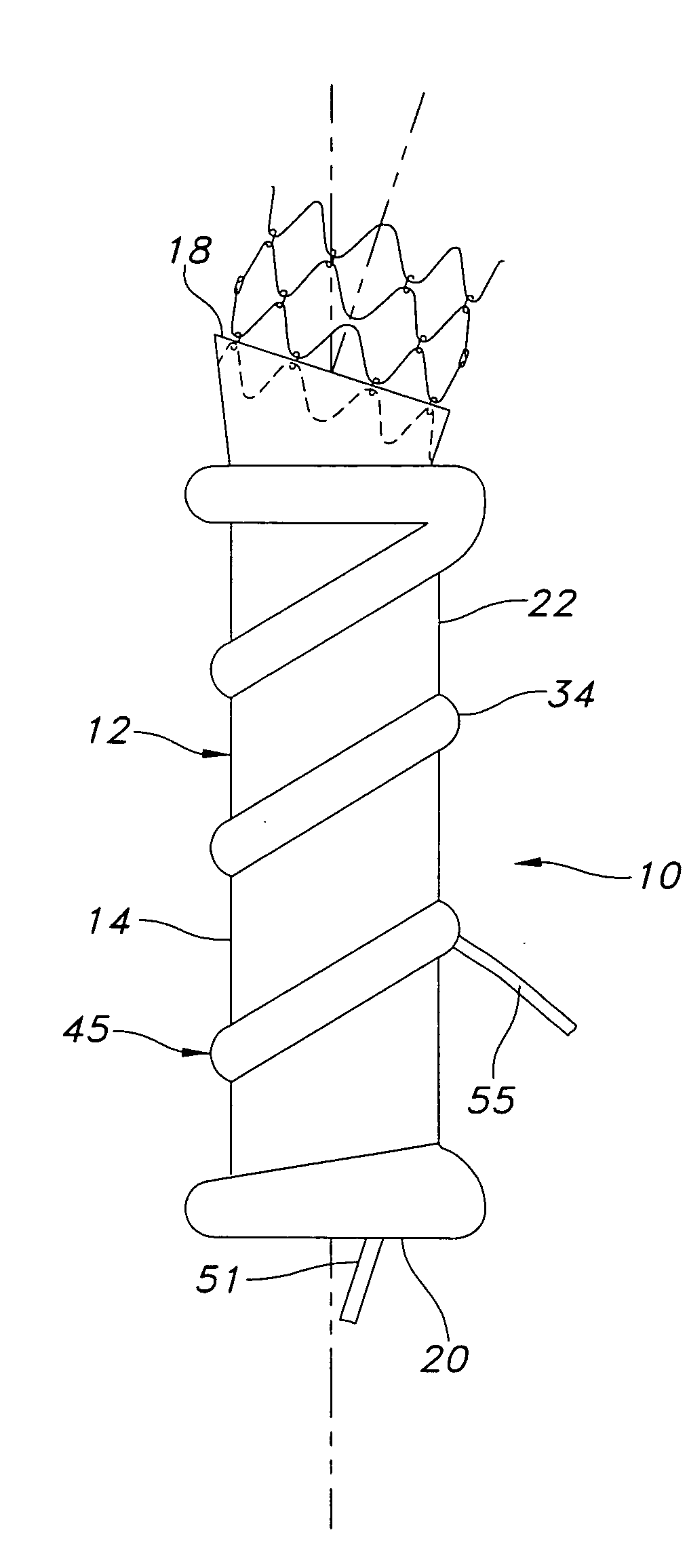
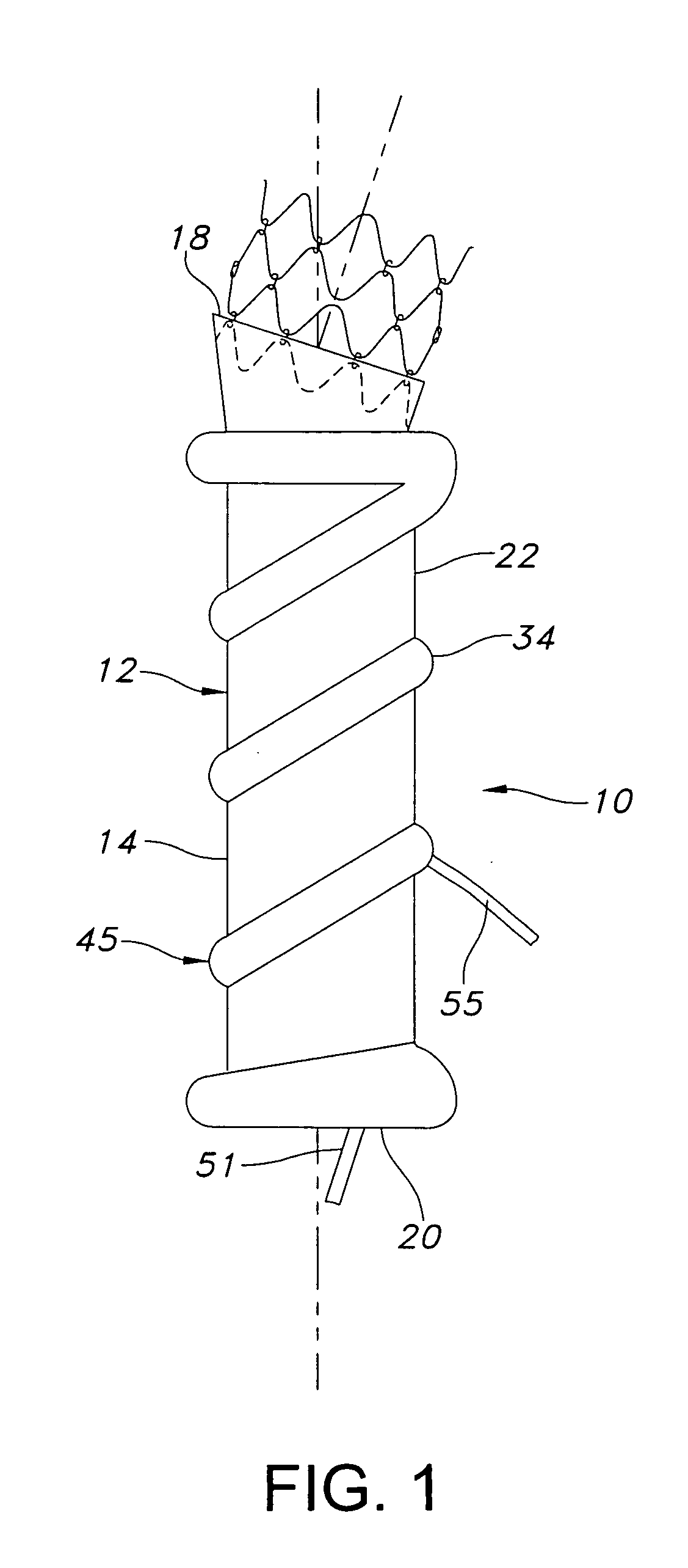
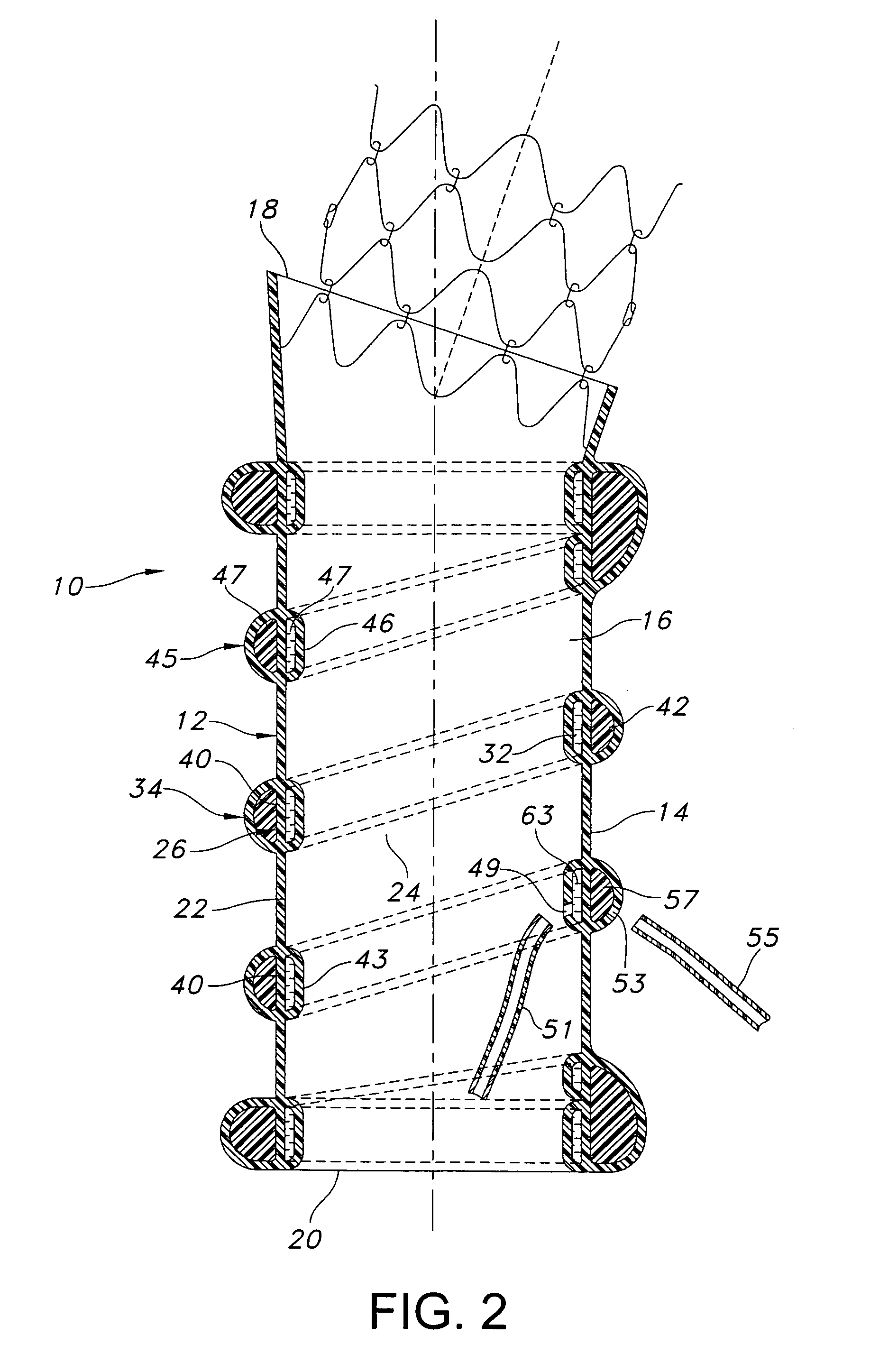
[0016]Referring to the drawings and more specifically to FIGS. 1 and 2, the endovascular graft 10 includes a tubular structure 12 having an outer surface 14 and an inner surface 16. The tubular structure 12 has a first end 18 and a second end 20. The tubular structure 12 has a wall 22 which defines a lumen 24 between the first and second ends 18, 20.

[0017]The endovascular graft 10 includes an elongate circumferential intermediate layer 26 which has a first transverse edge 28 and a second transverse edge 30, as shown in FIG. 3. The first and second transverse edges 28, 30 are attached to the outer surface 14 such that a circumferential inner chamber 32 is defined between the outer surface and intermediate layer 26. The tubular structure 12 has an annular portion 43 the outer surface of which coincides with the section of the outer surface 14 which constitutes a portion of the enclosure of the inner chamber 32.

[0018]The endovascular graft 10 includes an elongate circumferential outer ...


PUM


Abstract

The endovascular graft includes a dual chamber cuff structure. The endovascular graft includes a tubular structure having a first end and a second end. The tubular structure has a wall defining a lumen between the first and second ends. The endovascular graft includes a cuff circumferentially secured to the tubular structure. The cuff has an interior cavity which is bifurcated such that the interior cavity includes a circumferential outer chamber and a circumferential inner chamber. The method for forming the endovascular graft includes inserting an expansion substance into the inner chamber to resist a luminal intrusion of the tubular structure resulting from the insertion of the expansion substance into the outer chamber. The expansion substance within the outer chamber is stiffened. The expansion substance within the inner chamber is removed.

Description

FIELD OF THE INVENTION[0001]The present invention relates generally to an expandable cuff for an endovascular graft, and a method for forming the same. More specifically, the present invention relates to an expandable cuff which has two chambers to limit luminal intrusion of the cuff within the graft.BACKGROUND OF THE INVENTION[0002]Endovascular grafts are known for treating disorders of the vasculature. Such endovascular grafts may include a tubular structure and one or more circumferential cuffs secured thereto. Such circumferential cuffs may be near the proximal or distal ends of the tubular structure. The cuffs may be expandable, which allows the cuffs to have a non-expanded condition in which the cuffs have a reduced diameter and profile. Such a reduced diameter and profile of the cuffs facilitates deployment thereof and the tubular structure into and through the vasculature of the patient by a delivery system, such as may include a catheter. Following the completion of the pos...

Claims


Application Information

Patent Timeline
Patent Type & Authority Applications(United States)
IPC IPC(8): A61F2/06
CPCA61F2/07A61F2002/075A61F2/89A61F2/88A61F2250/0003
Inventor KARI, STUART E.
Owner TRIVASCULAR2
Why Eureka
Try Eureka