Telescope Mount

a technology for telescopes and mounts, applied in the field of telescope mounts, can solve the problems of limiting the handling and movability of telescopes, affecting the positioning and guiding precision of telescopes, and high materials costs and high costs, and achieves the effects of simple and pollution-free, high positioning accuracy, and precise guiding

Inactive Publication Date: 2008-03-13
ANIOL PETER +1
View PDF5 Cites 8 Cited by
  • Summary
  • Abstract
  • Description
  • Claims
  • Application Information

AI Technical Summary

Benefits of technology

[0020] The apparatus may be used for the attachment of a telescope. Thereby the telescope can be mounted at only one side of the apparatus. The mount may provide only a single connection, for example a single flange for mounting a telescope. A time consuming and difficult alignment, for example in a double-tine fork can be avoided and mounting or exchanging of the telescope optics is much easier and faster using the apparatus of the invention. The apparatus of the invention can also have one telescope flange for each telescope to be mounted to the apparatus.
[0036] The housing can provide attachment means by which the housing of a first rotation device can be attached to a stand or support or to a polar adjustment. The working shaft of the first rotation device can be attached or can be attachable to the housing of a second rotation device. The attachment is such that the working shaft of the first rotation device and the working shaft of the second rotation device are oriented perpendicular with respect to each other when the first rotation device and the second rotation device are mounted to each other. The optics of a telescope can be mounted or attached to the working shaft of the second rotation device. Fast attachment mechanisms or standardized fixation devices can be provided so that an easy and fast exchange of the optics or the telescope is possible. The apparatus or mount according to the invention can thus be used with different telescopes or optical devices.

Problems solved by technology

Commonly known drives, by which the force is transmitted via gears, for example worm gears, onto the shaft, have mechanical disadvantages which have a negative influence on the positioning and guiding precision of the mount, i.e., caused by periodic worm gear errors, internal backlash or gear backlash, hysteresis when inverting the direction of rotation, different friction for example in different operating temperatures (telescopes are often used outside), and others.
In case it is desired to optimize high positioning velocities and positioning accuracy at the same time, a high constructive effort is necessary in systems according to the state of the art, for example by optimizing transmissions or gears and of the regulating motors, leading to high costs and expensive materials.
In addition, transmissions and motors attached to the housing of the mount are often very large in size and can limit the handling and the movability of the telescope.

Method used


Image

  • Telescope Mount
  • Telescope Mount
  • Telescope Mount

Examples


Embodiment Construction

[0046] In the following description of an exemplary embodiment of the invention, equal or similar elements are described with the same references.

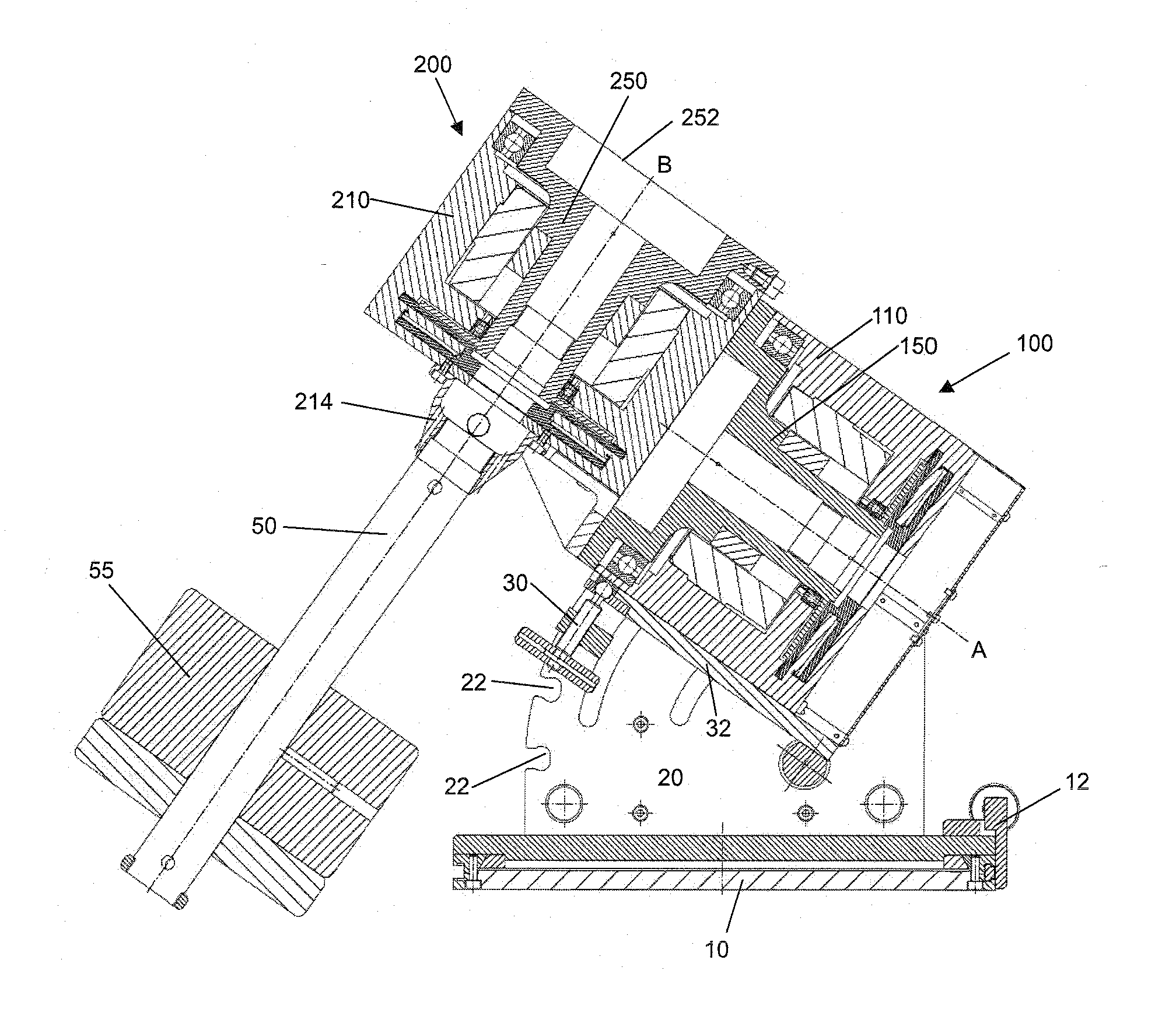
[0047]FIG. 1 shows a telescope mount according to the invention. The mount is shown in equatorial configuration; it is evident to a person skilled in the art that the mount shown can also be used and configured as an Alt-Azimuth mount or as an Alt-Alt mount.

[0048] The mount has a base 10 by which the mount can be mounted or connected to a stand or another support. The base 10 can have a rotation means being fixable by a locking device and being adjustable by a Vernier adjustment 12 and by which the mount is arranged rotating about the vertical axis. Typically the mount is adjusted once in the azimuth corresponding to the geographic position of the observation position and remains for the total observation period in this adjusted position. A polar adjustment 20 is provided on the base 10 which allows to adjust a first rotation element 100...


PUM


Abstract

Apparatus for the rotatable mount of a telescope having at least two axes being substantially orthogonal to each other, wherein the telescope is rotatable about at least a first axis of the two orthogonal axes by at least a first rotation device, the rotation device comprising a first working shaft and a first driven shaft of a first drive wherein the respective axis of the first working shaft and the first driven shaft are aligned and formed integrally.

Description

CROSS-REFERENCE TO RELATED APPLICATIONS [0001] The present application claims priority to and the benefit of the filing date of European Patent Application Serial No. EP 06 019 000.6 filed on Sep. 11, 2006. STATEMENT REGARDING FEDERALLY SPONSORED RESEARCH OR DEVELOPMENT [0002] None. BACKGROUND OF THE INVENTION [0003] 1. Field Of The Invention [0004] The present invention relates to telescope mounts. In particular, the invention relates to motor driven telescope mounts. [0005] 2. Brief Description Of The Related Art [0006] Telescopes of any size for the observation of the sky and stars from the earth are usually rotatably mounted by means of at least two axes. Telescope mounts are used on one hand to direct the telescope quickly to an object, i.e., a celestial object to be observed and on the other hand to observe this object over a continued period of time independently of the rotation of the earth. Systems for continuous observation of a celestial object are known, by which the tel...

Claims


Application Information

Patent Timeline
Patent Type & Authority Applications(United States)
IPC IPC(8): G02B23/16
CPCG02B23/165
Inventor ANIOL, PETERCOSTANTINO, MARIO
Owner ANIOL PETER
Why Eureka
Try Eureka