HP turbine blade airfoil profile

Active Publication Date: 2008-03-13
PRATT & WHITNEY CANADA CORP
View PDF8 Cites 41 Cited by
  • Summary
  • Abstract
  • Description
  • Claims
  • Application Information

AI Technical Summary

Benefits of technology

[0008]The profile shape of the present invention provides maximum work for a two-stage high pressure turbine, while minimizing flow separation disadvantages in such an environment. It is also necessary to give consideration to the downstream component (in this case, the LP turbine), to ensure that it can accept the flow conditions as they leave the HP turbine, without any adverse effect on LPT performance. The exit conditions of this HPT must be optimized such that the flow can negotiate the flow path in the infer-turbine

Problems solved by technology

Over and above this, the airfoil is subject to flow regimes which lend themselves easily to flow separation, which tend to limit the amount of work transferred to the compressor, and hence the

Method used


Image

  • HP turbine blade airfoil profile
  • HP turbine blade airfoil profile
  • HP turbine blade airfoil profile

Examples


Embodiment Construction

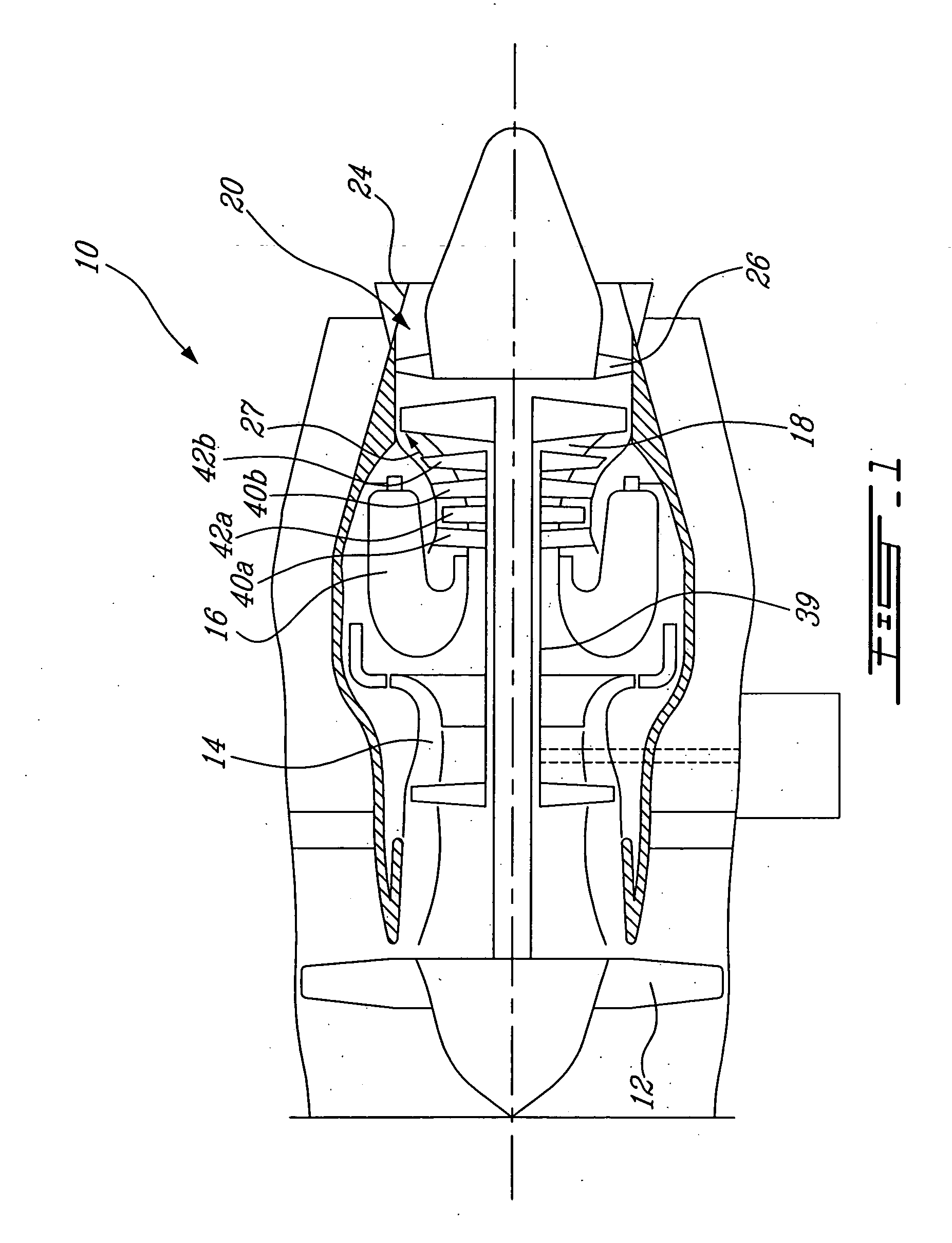
[0015]FIG. 1 illustrates a gas turbine engine 10 of a type preferably provided for use in subsonic flight, generally comprising in serial flow communication a fan 12 through which ambient air is propelled, a multistage compressor 14 for pressurizing the air, a combustor 16 in which the compressed air is mixed with fuel and ignited for generating an annular stream of hot combustion gases, and a turbine section 18 for extracting energy from the combustion gases to drive the fan, the compressor, and produce thrust.

[0016]The gas turbine engine 10 further includes a turbine exhaust duct 20 which is exemplified as including an annular core portion 22 and an annular outer portion 24 and a plurality of struts 26 circumferentially spaced apart, and radially extending between the inner and outer portions 22, 24.

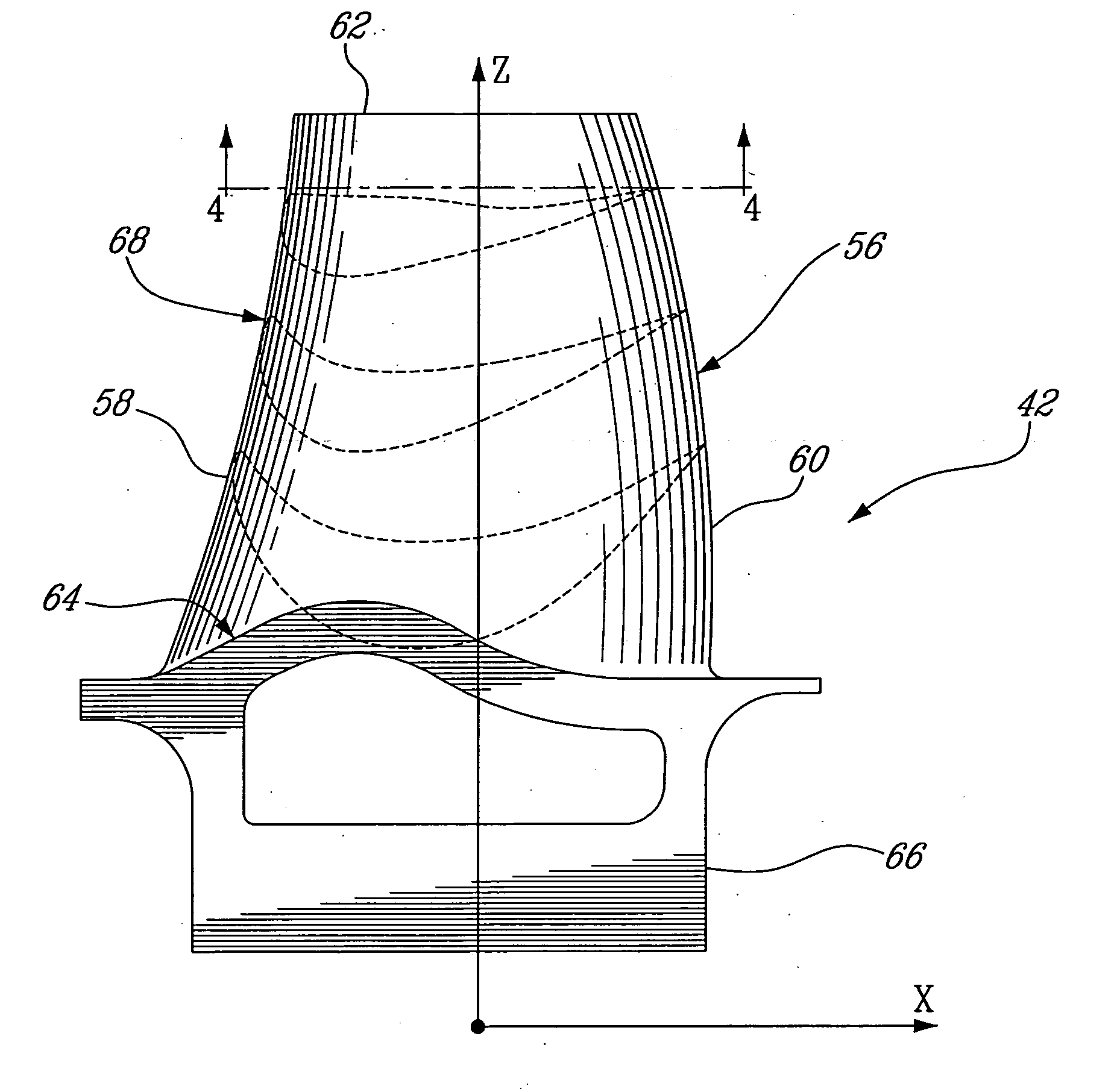
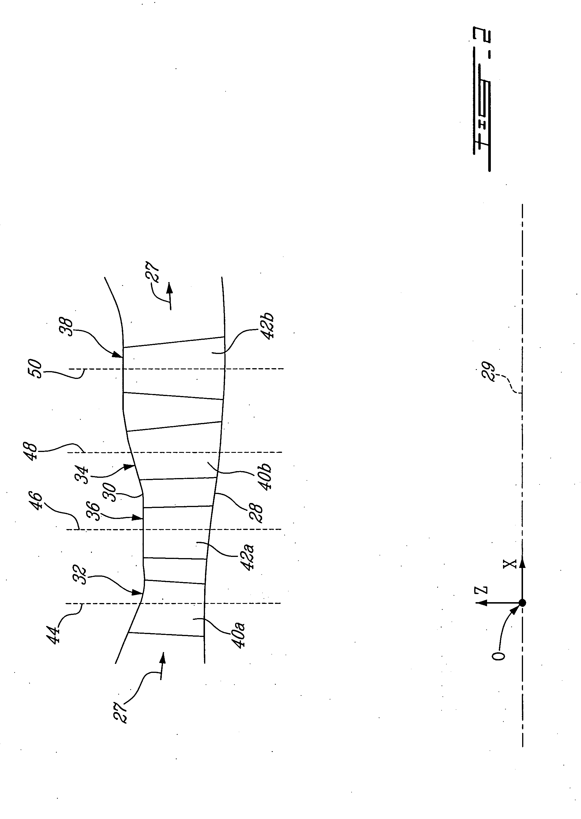
[0017]FIG. 2 illustrates a portion of an annular hot gaspath, indicated by arrows 27 and defined by annular inner and outer walls 28 and 30 respectively, for directing the stream of ho...


PUM


Abstract

A second stage blade of a two-stage high pressure turbine includes an airfoil having a profile substantially in accordance with at least an intermediate portion of the Cartesian coordinate values of X, Y and Z set forth in Table 2. The X and Y values are distances, which when smoothly connected by an appropriate continuing curve, define airfoil profile sections at each distance Z. The profile sections at each distance Z are joined smoothly to one another to form a complete airfoil shape.

Description

TECHNICAL FIELD[0001]The invention relates generally to a blade airfoil for a gas turbine engine and, more particularly, to an airfoil profile suited for use in the second stage rotor assembly of a two-stage high pressure turbine.BACKGROUND OF THE ART[0002]Where a blade airfoil is part of a two-stage turbine driving a compressor (i.e. part of a high pressure or HP turbine), the requirements for such a blade airfoil design are significantly more stringent than multiple stage airfoil designs, as the compressor relies solely on this two-stage HP turbine to deliver all the required work, as opposed to work being spread over several turbine stages. Over and above this, the airfoil is subject to flow regimes which lend themselves easily to flow separation, which tend to limit the amount of work transferred to the compressor, and hence the total thrust or power capability of the engine. The HP turbine is also subject to harsh temperatures and pressures, which require a solid balance betwee...

Claims


Application Information

Patent Timeline
IPC IPC(8): F01D5/14
CPCF05D2250/74F01D5/141
Inventor SREEKANTH, SRIVLASIC, EDWARDGIRGIS, SAMI
Owner PRATT & WHITNEY CANADA CORP
Why Eureka
Try Eureka