Ultrasonic Dental Tool

a technology of dental tools and ultrasonic waves, applied in the field of ultrasonic dental tools, can solve the problems of multiple inserts and handpieces, increased risk, and difficulty in seeing well into all regions of the mouth under the best of conditions, so as to improve the utilization of alternating current, reduce the variation in voltage, and increase the lifespan of light sources

Inactive Publication Date: 2008-03-13
DISCUS DENTAL LLC
View PDF15 Cites 33 Cited by
  • Summary
  • Abstract
  • Description
  • Claims
  • Application Information

AI Technical Summary

Benefits of technology

[0012] In one aspect, the ultrasonic dental insert includes a sheath. The sheath may be formed such that it may cover at least part of the handpiece housing. In general, the sheath may serve as a barrier such that it may reduce cross-contamination to and from the patient's mouth. The insert may, for example, be sterilized prior to use by methods such as autoclaving, alcohol sterilization, and / or any other appropriate method such that when the sheath covers the handpiece, it provides a sterile surface that may be inserted into the patient's mouth. The ultrasonic dental tool may then be used such that it is not necessary for the handpiece to be sterilized. The sheath may also help to prevent contaminants from one patient's mouth from being transferred to another patient or to the work area of the handpiece.
[0044] In some aspects, an output smoothing circuit may also be included in the circuitry of the illumination energy coil and light source that may effectively reduce the variation in voltage over the time of use and may thus increase the lifespan of the light source as well as reduce any variations in the amount of light delivered to the field of work. An output smoothing circuit may include a Zener diode, a reservoir capacitor, a capacitor-input filter and / or any other appropriate circuit element(s) that may effectively reduce variations in the voltage over time at the light source.

Problems solved by technology

This results in multiple inserts and handpieces being needed to maintain steady work flow and sterilizations.
Since a mouth is a small space in which to work, it is often difficult to see well into all regions of the mouth under the best of conditions.
When a dental practitioner cannot see clearly in the field of work, it is more likely that painful slips can occur.
The often sharp implements, vibrating at ultrasonic frequencies, can do considerable harm to soft tissue (such as gum tissue) resulting in bleeding and pain.
The large and focused lamp that hangs over the field of work while the dental practitioner uses ultrasonic dental tools in the patient's mouth often becomes obscured when the dental practitioner leans closely toward the patient to work in confined spaces within the mouth.
The suddenly darker field is more difficult in which to work accurately.
Small slips and injuries can result.

Method used


Image

  • Ultrasonic Dental Tool
  • Ultrasonic Dental Tool
  • Ultrasonic Dental Tool

Examples


Embodiment Construction

[0078] The detailed description set forth below is intended as a description of the presently exemplified device provided in accordance with aspects of the present invention and is not intended to represent the only forms in which the present invention may be practiced or utilized. It is to be understood, however, that the same or equivalent functions and components may be accomplished by different embodiments that are also intended to be encompassed within the spirit and scope of the invention.

[0079] Unless defined otherwise, all technical and scientific terms used herein have the same meaning as commonly understood to one of ordinary skill in the art to which this invention belongs. Although any methods, devices and materials similar or equivalent to those described herein can be used in the practice or testing of the invention, the exemplified methods, devices and materials are now described.

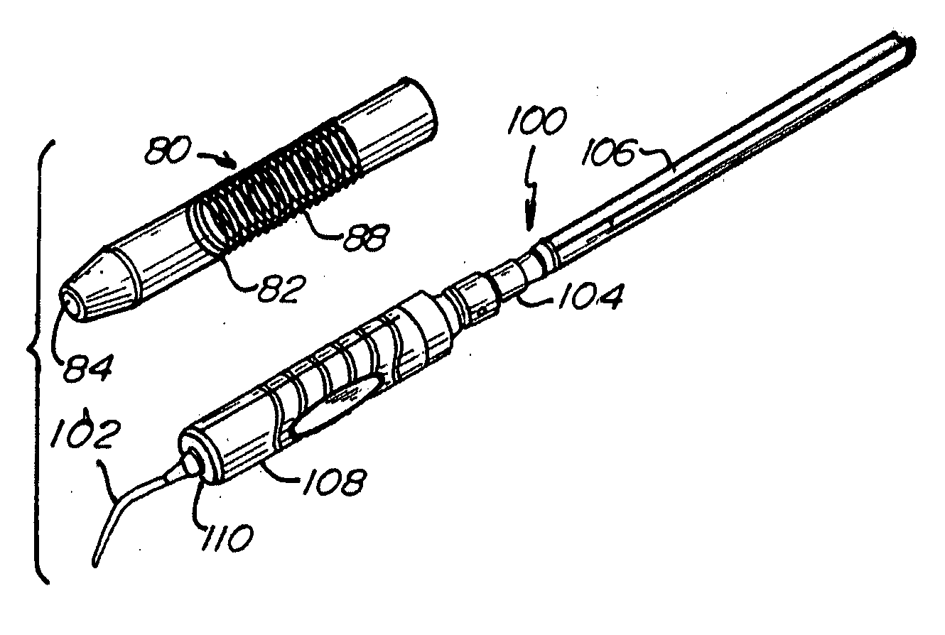
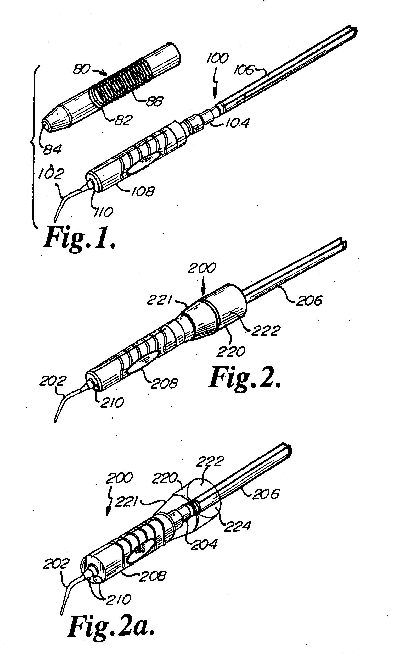
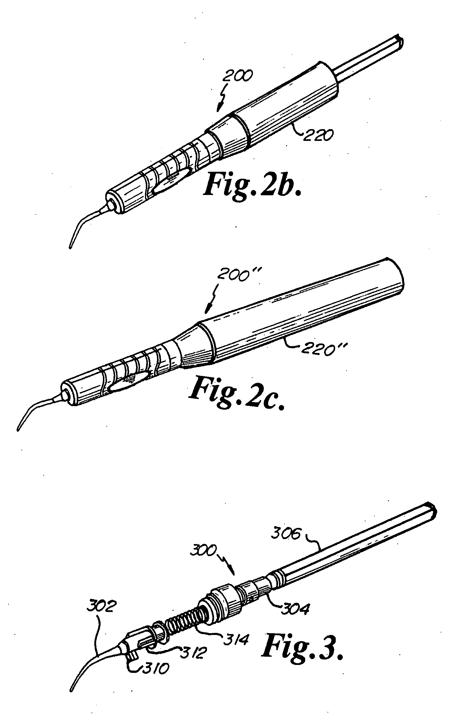
[0080] The present invention relates to ultrasonic dental tools having an integral shea...


PUM


Abstract

The present invention relates to ultrasonic dental tools having an integral sheath and at least one light source adapted to utilize the electromagnetic energy already available in the existing ultrasonic dental unit. The handpiece includes a substantially hollow housing having a primary power source that may include a coil. In one aspect, the ultrasonic dental insert includes a sheath. The sheath may be formed such that it may cover at least part of the handpiece housing. In general, the sheath may serve as a barrier such that it may reduce cross-contamination to and from the patient's mouth. During operation, the primary coil of the handpiece may be inductively coupled to an illumination energy coil such that the illumination energy coil may draw energy from the electromagnetic field of the primary coil to power at least one light emitting element.

Description

CROSS-REFERENCE TO RELATED APPLICATIONS [0001] This application claims the benefit of U.S. provisional application Ser. Nos. 60 / 838,581, filed 17 Aug. 2006, entitled “ULTRASONIC DENTAL TOOL HAVING A LIGHT SOURCE”; 60 / 838,579, filed 17 Aug. 2006, entitled “ULTRASONIC DENTAL TOOL HAVING A LIGHT SOURCE”; 60 / 838,607, filed 17 Aug. 2006, entitled “ULTRASONIC DENTAL TOOL HAVING A LIGHT SOURCE”; 60 / 838,576, filed 17 Aug. 2006, entitled “ULTRASONIC DENTAL TOOL HAVING A LIGHT SOURCE”; 60 / 945,345, filed 20 Jun. 2007, entitled “ULTRASONIC DENTAL TOOL”; and 60 / 946,125, filed 25 Jun. 2007, entitled “ULTRASONIC DENTAL TOOL”, the contents of all of which are hereby incorporated by reference.FIELD OF THE INVENTION [0002] The present invention is related to ultrasonic dental tools, and particularly to ultrasonic dental tools having at least one light source and / or a sheath. BACKGROUND OF THE INVENTION [0003] Dental practitioners use ultrasonic dental tools (instruments) for dental treatments and pro...

Claims


Application Information

Patent Timeline
Patent Type & Authority Applications(United States)
IPC IPC(8): A61C1/07
CPCA61C17/20A61C1/0015A61C2204/002
Inventor QUAN, CHRISTOPHERFANI, PEJMANSTEIN, GREGORYPHAM, TRAVISZARGARI, BRIAN
Owner DISCUS DENTAL LLC
Why Eureka
Try Eureka