

Frequency divider monitor of phase lock loop
a technology of phase lock loop and frequency divider, which is applied in the direction of automatic control, electrical equipment, etc., can solve the problems of inability to supply clock signals to the integrated circuit or electronic system that supplies the clock signal, and frequency dividers are one of the most prone to failur
- Summary
- Abstract
- Description
- Claims
- Application Information
AI Technical Summary
Problems solved by technology
Method used
Image

Examples
first embodiment
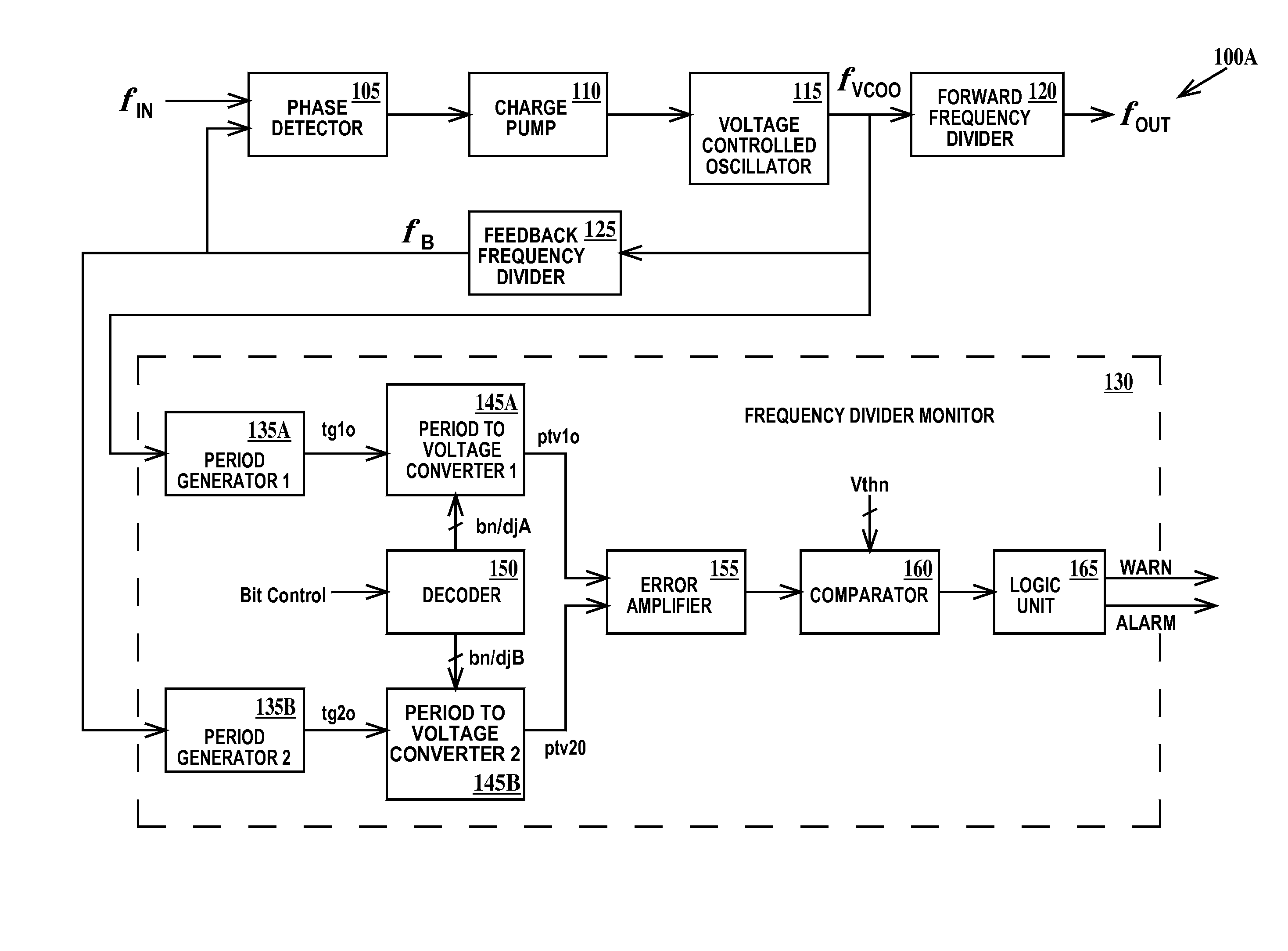
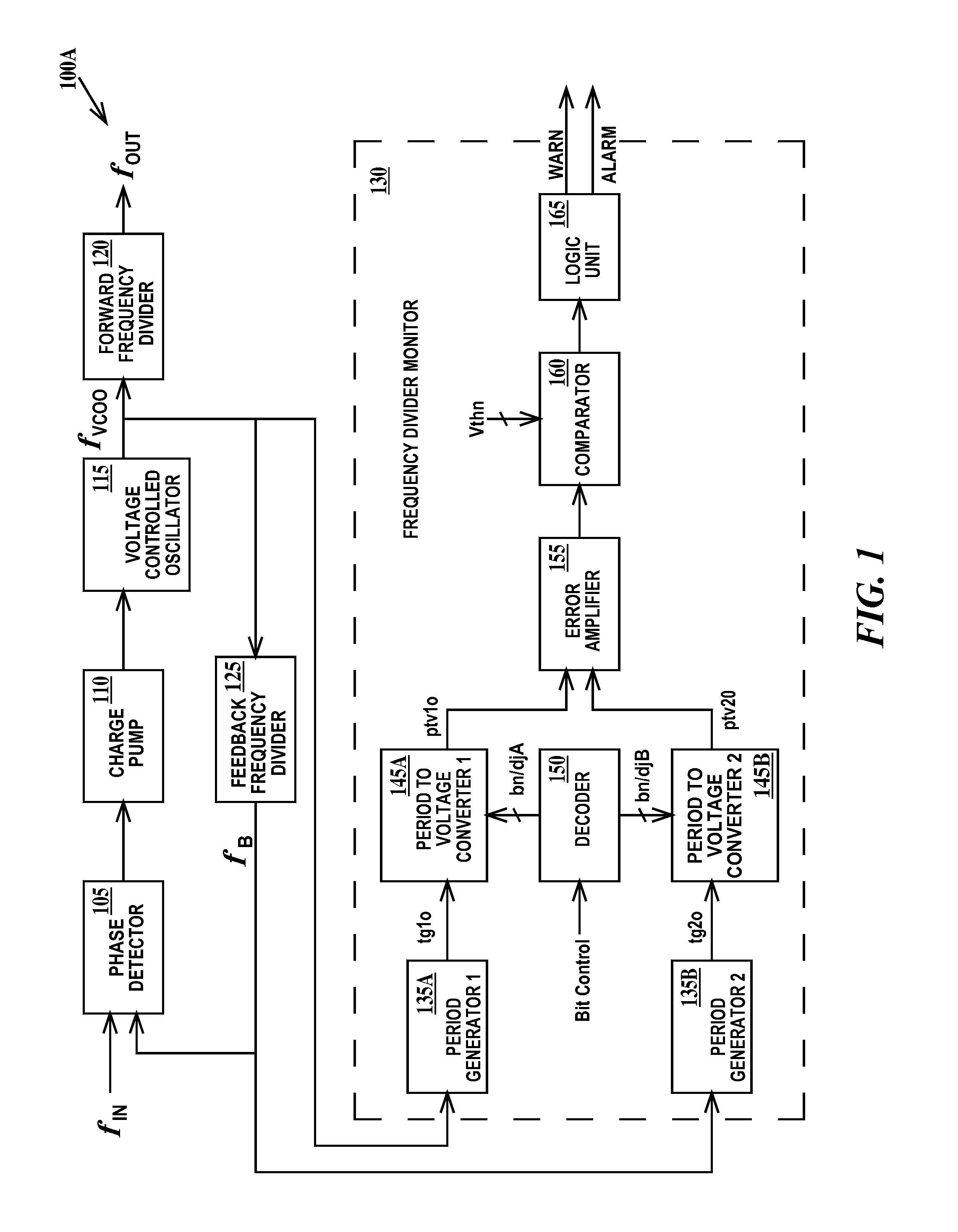
[0023]FIG. 1 is the block circuit diagram of a first frequency generator and monitor circuit 100A according to the present invention. In FIG. 1, frequency generator and monitor circuit 100A includes a phase locked loop circuit which includes a phase detector 105, a charge pump 110, a voltage controlled oscillator 115 which generates a clock signal fVCOO, a forward frequency divider 120 (which is optional) which generates a clock signal fOUT and a feedback frequency divider 125 which generates a clock signal fB.
[0024] A first input of phase detector 105 is connected to clock signal fIN and a second input of the phase detector is connected to an output (fB) of feedback frequency divider 125. An output of phase detector 105 is connected to an input of charge pump 110. An output of charge pump 110 is connected to and input of voltage controlled oscillator 115. An output (fVCOO) of voltage controlled oscillator 115 is connected to an input of forward frequency divider 120 and an input of...
second embodiment
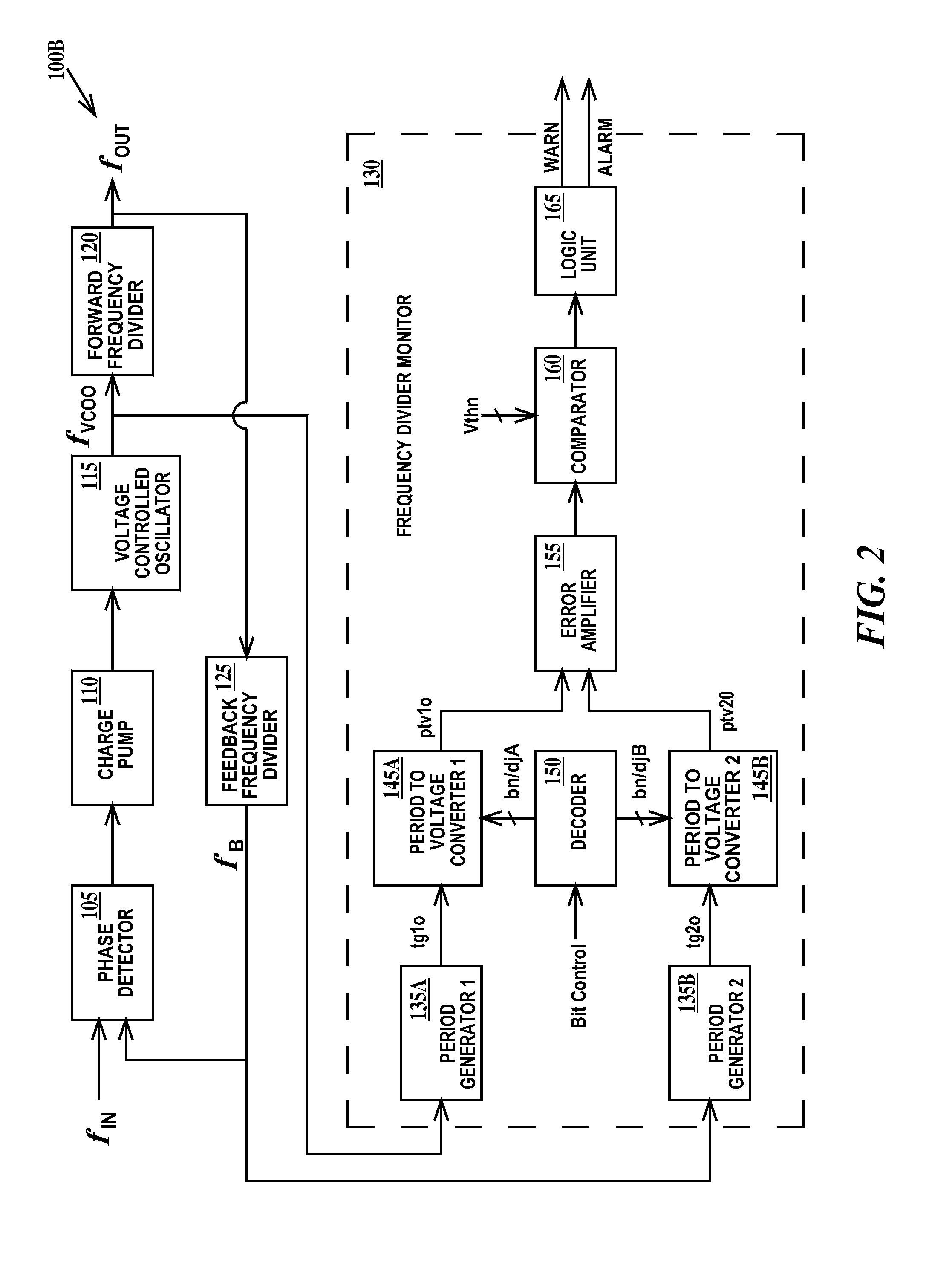
[0031]FIG. 2 is block circuit diagram of a second frequency generator and monitor circuit 110B according to the present invention. Frequency generator and monitor circuit 110B is similar to frequency generator and monitor circuit 110A (see FIG. 1) except the input of feedback frequency divider 125 is connected to the output of forward frequency divider 120 instead of the output of voltage controlled oscillator 115 (see FIG. 1).
[0032] Operation of frequency generator and monitor circuit 110B is similar to the operation of frequency generator and monitor circuit 110A (see FIG. 1), but because the output (fVCOO) of forward frequency divider 120 is presented to the input of feedback frequency divider 125, the value R includes the divide ratio of forward frequency divider 120 and the divide ratio of feedback frequency divider 125. So both forward frequency divider 120 and feedback frequency divider 125 are monitored by frequency divider monitor 130.
third embodiment
[0033]FIG. 3 is block circuit diagram of a third frequency generator and monitor circuit 110C according to the present invention. Frequency generator and monitor circuit 110C is similar to frequency generator and monitor circuit 110B (see FIG. 2) except the input of feedback frequency divider 125 is connected to the output of external frequency divider 170 instead of to the output of forward frequency divider 120 (see FIG. 2) and the input of external frequency divider 170 is connected to the output of forward frequency divider 120.
[0034] Operation of frequency generator and monitor circuit 110B is similar to the operation of frequency generator and monitor circuit 110B (see FIG. 2), but because the output (fVCOO) of forward frequency divider 120 is presented to the input of forward frequency divider 120, the output (fOUT) of forward frequency 120 is presented to the input of external frequency divider 170 and the output (fEXT) of external frequency divider 170 is presented to the i...
PUM
 Abstract
Description
Claims
Application Information