Phase-locked loop circuit

a phase-locked loop and circuit technology, applied in the direction of digital transmission, pulse automatic control, electrical apparatus, etc., can solve the problems of serial data stream being cut off instantly in reproduction, the lock point of signal reproduction tends to deviate, and the influence of various characteristics of the pll circuit, so as to increase the measurement resolution of offset correction and correction resolution, and high reliability

Active Publication Date: 2006-06-01
TEXAS INSTR INC
View PDF7 Cites 52 Cited by
  • Summary
  • Abstract
  • Description
  • Claims
  • Application Information

AI Technical Summary

Benefits of technology

[0017] As another preferred method of the present invention, in order to increase the measurement resolution of the offset correction and the correction resolution, the output terminal of the second comparator is connected via a second resistor to the inverting input terminal of the op amp, and a prescribed reference voltage is input to the non-inverting input terminal of the op amp. As another preferred method, the output terminal of the second comparator is connected to the non-inverting input terminal of the op amp, and a prescribed reference voltage is input to the inverting input terminal of the op amp. In this case, as the reference voltage is fed from a reference voltage generator via a third resistor to the inverting input terminal of the op amp, it is possible to further increase the measurement resolution of offset correction and the correction resolution.
[0018] Also, as a preferred method of the present invention, the first comparator has a frequency comparing circuit that compares the frequency of the input signal to the frequency of the clock, and outputs the frequency error signal corresponding to the comparison error, and a phase comparing circuit that compares the phase of the input signal and the phase of the clock, and outputs the phase error signal corresponding to the comparison ...

Problems solved by technology

With the passive type filter, the variation in the control voltage is transmitted via the loop filter to the output of the phase comparing circuit, and has an adverse influence on the balance of the source current/sink current in the charge pump circuit, so that the lock point of the signal reproduction tends to deviate.
However, because the active type loop filter makes use of the op amp, the offset of the attached parts to the op amp has an adverse influence on the various characteristics of the PLL circuit, which is undesirable.
For this type of application, the problem is that the serial data stream may be cut off instantly in reproduction due to fingerprints, dirt, scratches, etc. on the surface of the optical disk.
However, if they go out of the lock range, frequency-locking deviates.
As a result, it is necessary to start the frequency-locked loop after the release of defect signal DF so as to pull in the frequency to start over again, and it takes a long time to re-establish phase locking.
As the time for re-establishing the phase locking becomes longer, during reproduction of CD or DVD playback, data may be skipped, causing audio gaps or freezi...

Method used


Image

  • Phase-locked loop circuit
  • Phase-locked loop circuit
  • Phase-locked loop circuit

Examples


Embodiment Construction

[0032] With the phase-locked loop circuit of the present invention, due to the aforementioned configuration and operation, the offset of the analog (especially the active type) loop filter is automatically corrected, the stability and precision of the locked clock or locked frequency are improved, and the reliability of the PLL function can be improved.

[0033] Optimum Scheme for Embodiment of the Invention

[0034] In the following, an explanation will be given regarding a preferred embodiment of the present invention with reference to the annexed drawings.

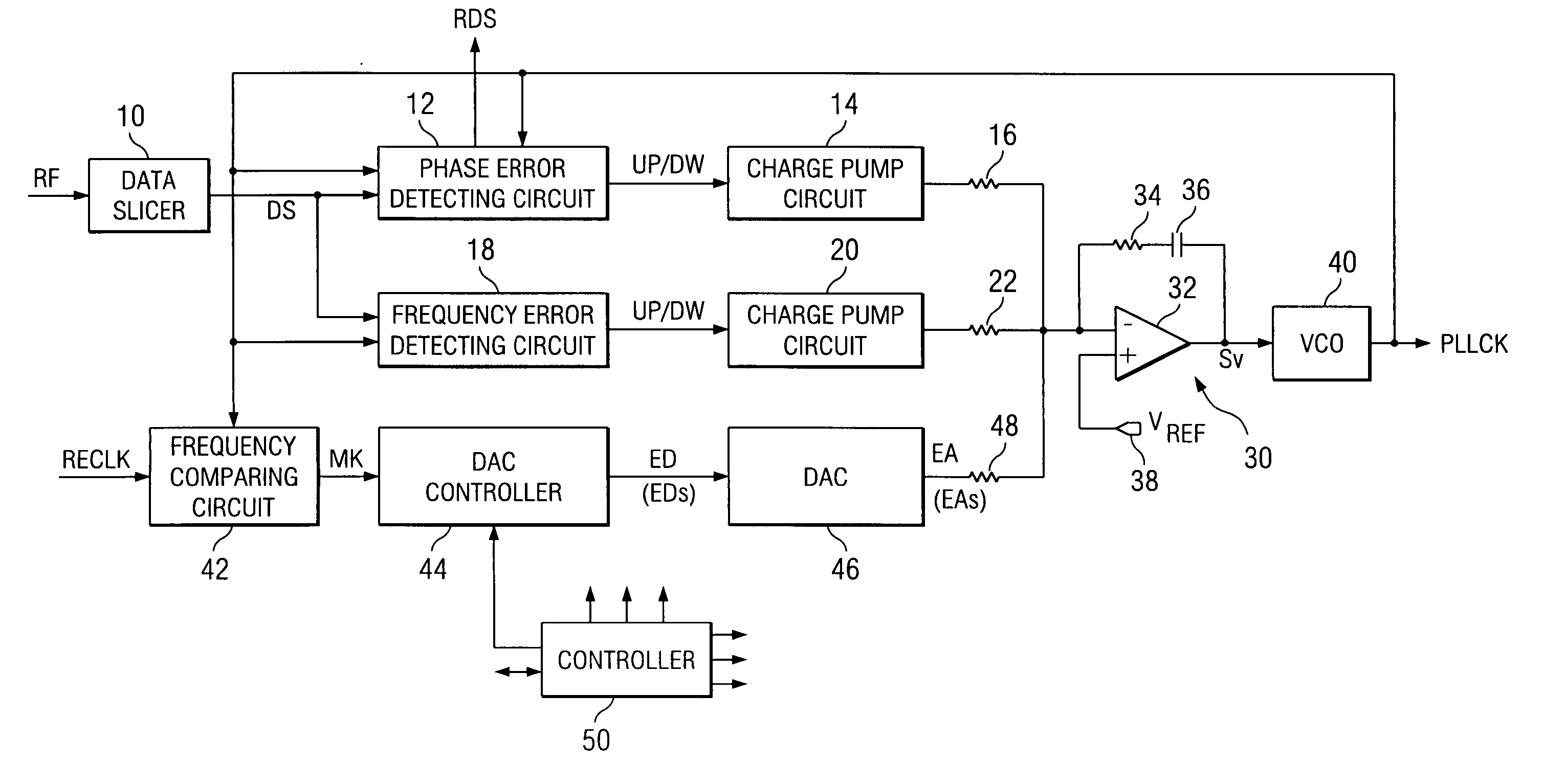
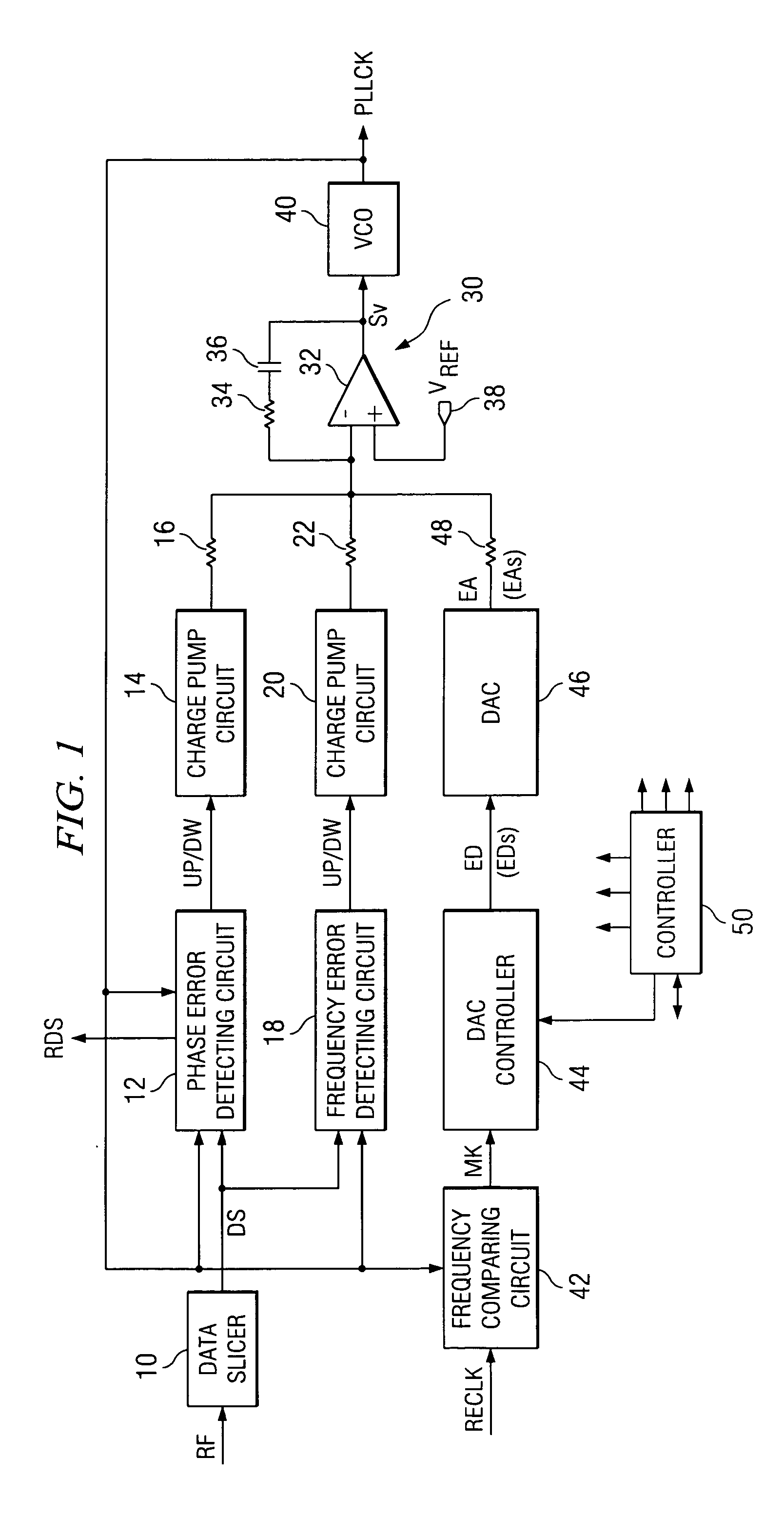
[0035]FIG. 1 is a diagram illustrating the configuration of the PLL circuit in an embodiment of the present invention. This PLL circuit is formed as a clock extraction type digital PLL circuit having an analog loop filter, and, for example, it can be applied to clock data recovery (CDR) during reproduction of optical disks, the as CDs and DVDs.

[0036] In data slicer 10 of the input section, for example, the reproduction RF signal (...


PUM


Abstract

A phase locked loop (PLL) circuit automatically corrects the offset of the analog (especially active type) loop filter to improve the stability and precision of the locked clock or frequency signals. In addition to the general PLL circuit configuration having active type loop filter (30), the PLL circuit also has a frequency comparing circuit (42), a DAC controller (44) and a DAC (digital-to-analog converter) (46). In an offset measurement mode, the outputs of phase error detecting circuit (12, 14) and frequency error detecting circuit (18, 20) are cut, respectively, to establish locking in offset measurement locked loop (42, 44, 45, 30, 40). In this case, offset correction code (EDs) are identified and held. In normal mode, DAC controller (44) has offset correction code (ED) input to DAC (46), and DAC (46) sends offset correction signal (EAs) to loop filter (30).

Description

[0001] The present invention relates to a phase-locked loop (PLL) circuit; and, in particular, to a PLL circuit that contains an analog loop filter. BACKGROUND OF THE INVENTION [0002]FIG. 5 illustrates the basic layout of a digital PLL circuit that contains an analog loop filter. This PLL circuit comprises a clock signal input / output type phase comparing circuit 100, an analog loop filter 102, and an analog input / output type voltage-controlled oscillator (VCO) 104. An input clock signal INCK and the feedback clock signal PLLCK output from VCO 104 are input to phase comparing circuit 100, which outputs analog phase error signal Φer representing the phase error of the two clock signals INCK, PLLCK. Loop filter 102 is a low-pass filter, which integrates phase error signal Φer output from phase comparing circuit 100. The output voltage of loop filter 102 is a control voltage Sv, which is input to VCO 104. VCO 104 oscillates and outputs variable frequency clock PLLCK whose frequency corr...

Claims


Application Information

Patent Timeline
IPC IPC(8): H03L7/00
CPCH03L7/087H03L7/10H04L7/0337H03L7/113
Inventor KOJIMA, HIROAKIMATSUSHIMA, ISAMU
Owner TEXAS INSTR INC
Why Eureka
Try Eureka