Object-point three-dimensional measuring system using multi-camera array, and measuring method

a three-dimensional measuring system and multi-camera array technology, applied in the field of three-dimensional measuring systems using multi-camera arrays, can solve the problems of single-point vision measuring methods, measurement blind spots, and the inability to quickly and accurately grasp the morphology characteristics of a whole measured object, and achieve the effect of quick and accurate measurement of dimensions

Active Publication Date: 2018-02-22
BEIJING QINGYING MACHINE VISUAL TECH CO LTD
View PDF0 Cites 21 Cited by
  • Summary
  • Abstract
  • Description
  • Claims
  • Application Information

AI Technical Summary

Benefits of technology

[0019]The present invention first provides a three-dimensional measuring system for measuring object points. The system uses a multi-camera group positione

Problems solved by technology

However, single-point vision measuring methods have disadvantages, particularly, the morphology characteristics of a whole measured object cannot be quickly and entirely grasped.
Further, in dynamic measurement, a quickly moving object will produce image deformation, resulting in measurement blind spots.
A drawback to planar vision measuring is that it can be hard to directly calculate physical dimensions of the object according to the pla

Method used


Image

  • Object-point three-dimensional measuring system using multi-camera array, and measuring method
  • Object-point three-dimensional measuring system using multi-camera array, and measuring method
  • Object-point three-dimensional measuring system using multi-camera array, and measuring method

Examples


Embodiment Construction

[0072]Below, the technical solutions and the methods of the present invention are further described in detail in conjunction with figures for understanding aspects of the present invention.

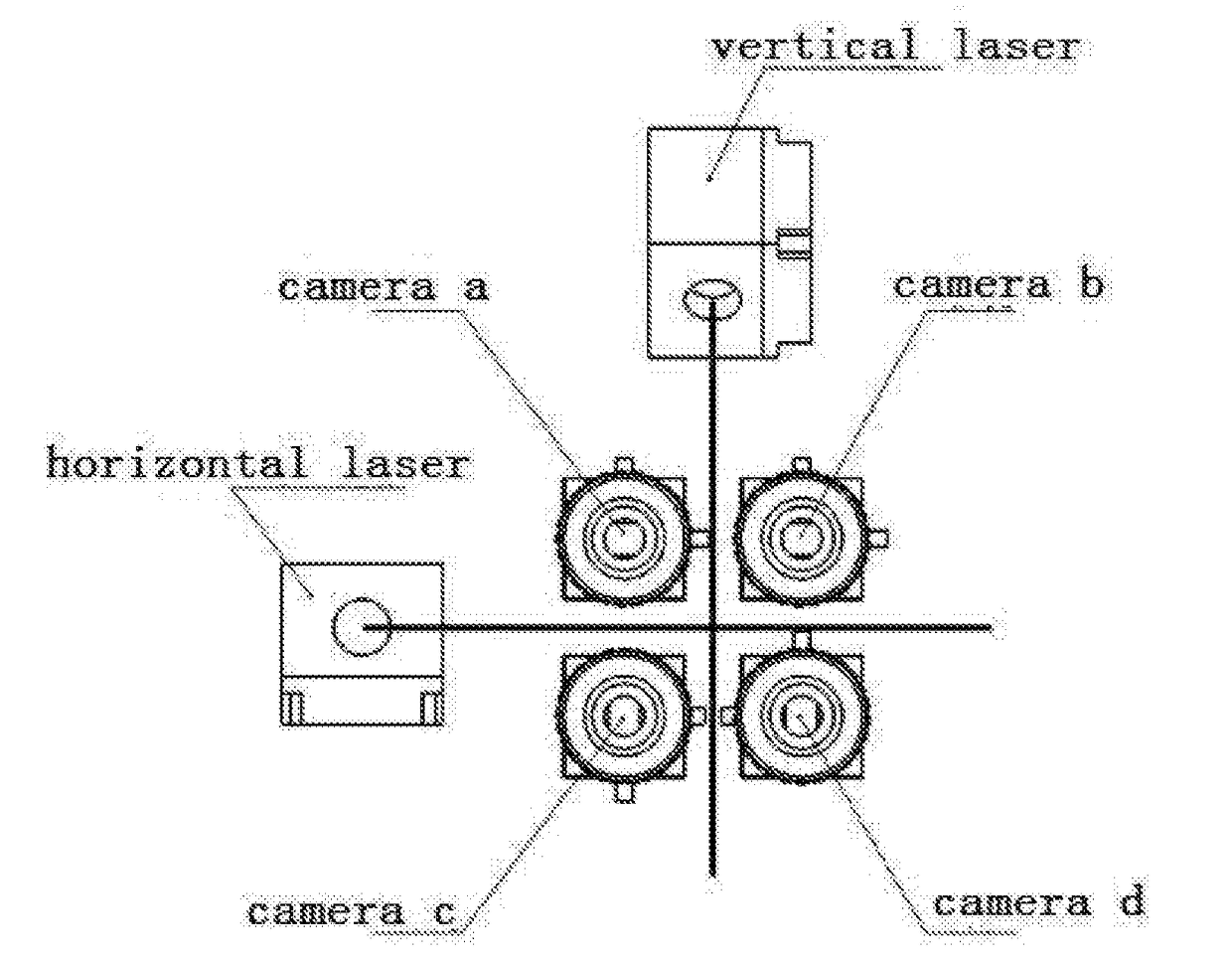
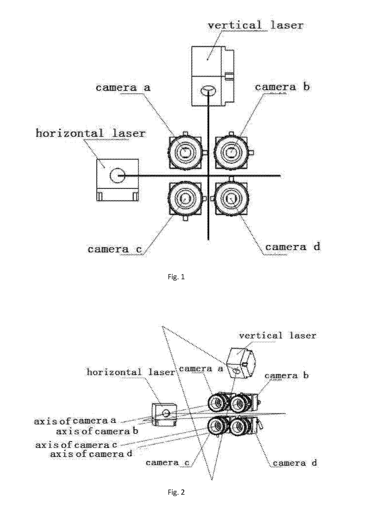
[0073]As shown in FIG. 1, FIG. 2, and FIG. 3, a three-dimensional measuring system using a multi-camera group is provided. The group of cameras is used to identify and measure object points on a three-dimensional object. The group is formed by an array of at least four digital cameras. In one aspect, the digital cameras are arranged in a 2×2 array. The digital cameras comprise a camera A, a camera B, a camera C and a camera D, wherein the cameras A, B, C and D are arranged on the same plane.

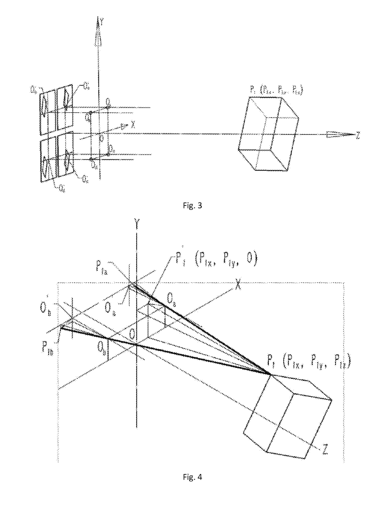
[0074]Focal points Oa, Ob, Oc, and Od on imaging optical axes of the four cameras (the camera A, the camera B, the camera C and the camera D), are on the same plane and form one rectangular shape, forming a rectangular plane. Cameras A, B, C and D are respectively located at four corners of the rectangular shap...


PUM


Abstract

A system for measuring object points on a three-dimensional object using a planar array of a multi-camera group, and a measuring method, are provided. The system is useful in the field of optical measuring technologies. The method includes establishing a measuring system of at least one four-camera group wherein digital cameras form a 2×2 array; matching an image object point acquired by the camera group; upon matched object point image coordinates, calculating coordinates of spatial locations of respective object points; upon coordinates of the spatial locations, calculating other three-dimensional dimensions of the measured object to be specially measured to form three-dimensional point clouds and establish a three-dimensional point clouds graph for performing three-dimensional stereoscopic reproduction. Here, full matching is performed for all measured points of the measured object by directly translating, superimposing, and comparing, point-by-point, the pixel points of measured images in X and Y-axes directions. In this way a three-dimensional object may be reproduced.

Description

CROSS REFERENCE TO RELATED APPLICATIONS[0001]This application claims the benefit of International Application PCT / CN2016 / 079274 filed Apr. 14, 2016. That application is entitled “Feature-Point Three-Dimensional Measuring System of Planar Array of Four-Camera Group and Measuring Method,” and is incorporated herein in its entirety by reference.[0002]This application also claims priority to Chinese national patent application CN 2016 / 10046181.0 filed on Jan. 22, 2016 and Chinese national patent application CN 2016 / 10131645.8 filed on Mar. 8, 2016.STATEMENT REGARDING FEDERALLY SPONSORED RESEARCH OR DEVELOPMENT[0003]Not applicable.THE NAMES OF THE PARTIES TO A JOINT RESEARCH AGREEMENT[0004]Not applicable.BACKGROUND OF THE INVENTION[0005]This section is intended to introduce various aspects of the art, which may be associated with exemplary embodiments of the present disclosure. This discussion is believed to assist in providing a framework to facilitate a better understanding of particul...

Claims


Application Information

Patent Timeline
IPC IPC(8): G01B11/25G01B11/00G01B11/03G01C11/02G06T7/557G06T7/593H04N13/02
CPCG01B11/2545G01B11/002G01B11/03G01C11/02G06T7/557G06T7/596H04N13/0275H04N13/0282G06T15/00G06T17/00G01B11/005G01B11/24G06T7/521H04N2013/0081H04N13/243G01B11/2518G01B11/254H04N13/271H04N13/275H04N13/282
Inventor YIN, XING
Owner BEIJING QINGYING MACHINE VISUAL TECH CO LTD
Why Eureka
Try Eureka