
Biological information measuring apparatus and method for controlling the apparatus

a technology of biological information and measuring apparatus, applied in the field of biological information measuring apparatus, can solve the problems of limited measurement accuracy, large apparatus size, and inability to avoid adverse effects of light crosstalk or outside light on measurement, and achieve rapid biological change, accurate and detailed manner, and rapid biological change

Active Publication Date: 2006-10-05
SPECTRATECH
View PDF5 Cites 21 Cited by
  • Summary
  • Abstract
  • Description
  • Claims
  • Application Information

AI Technical Summary

Benefits of technology

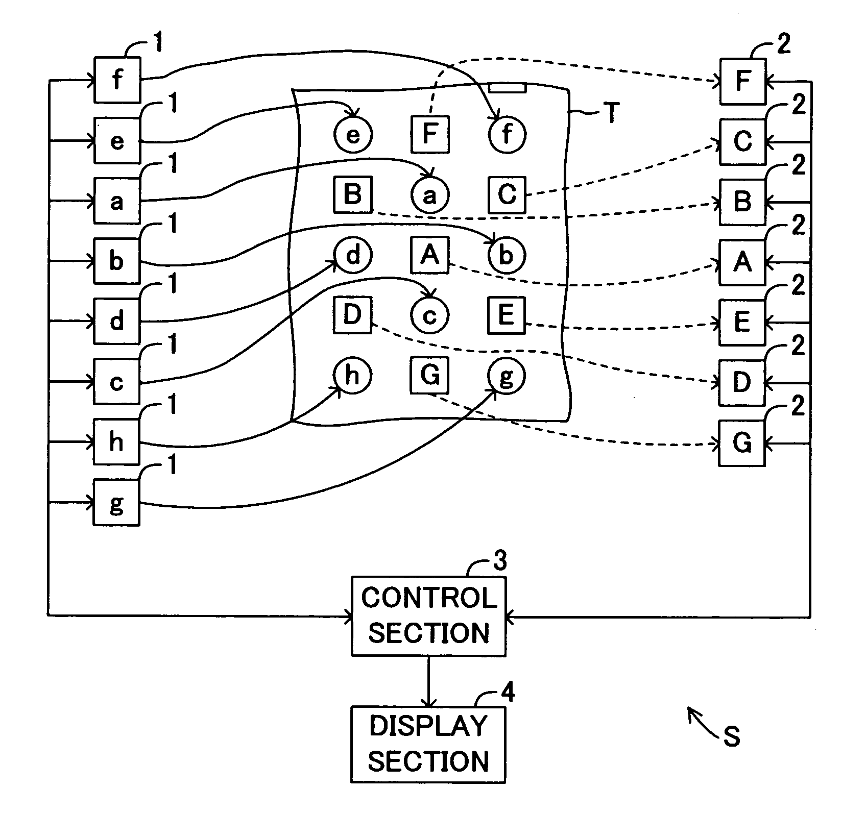
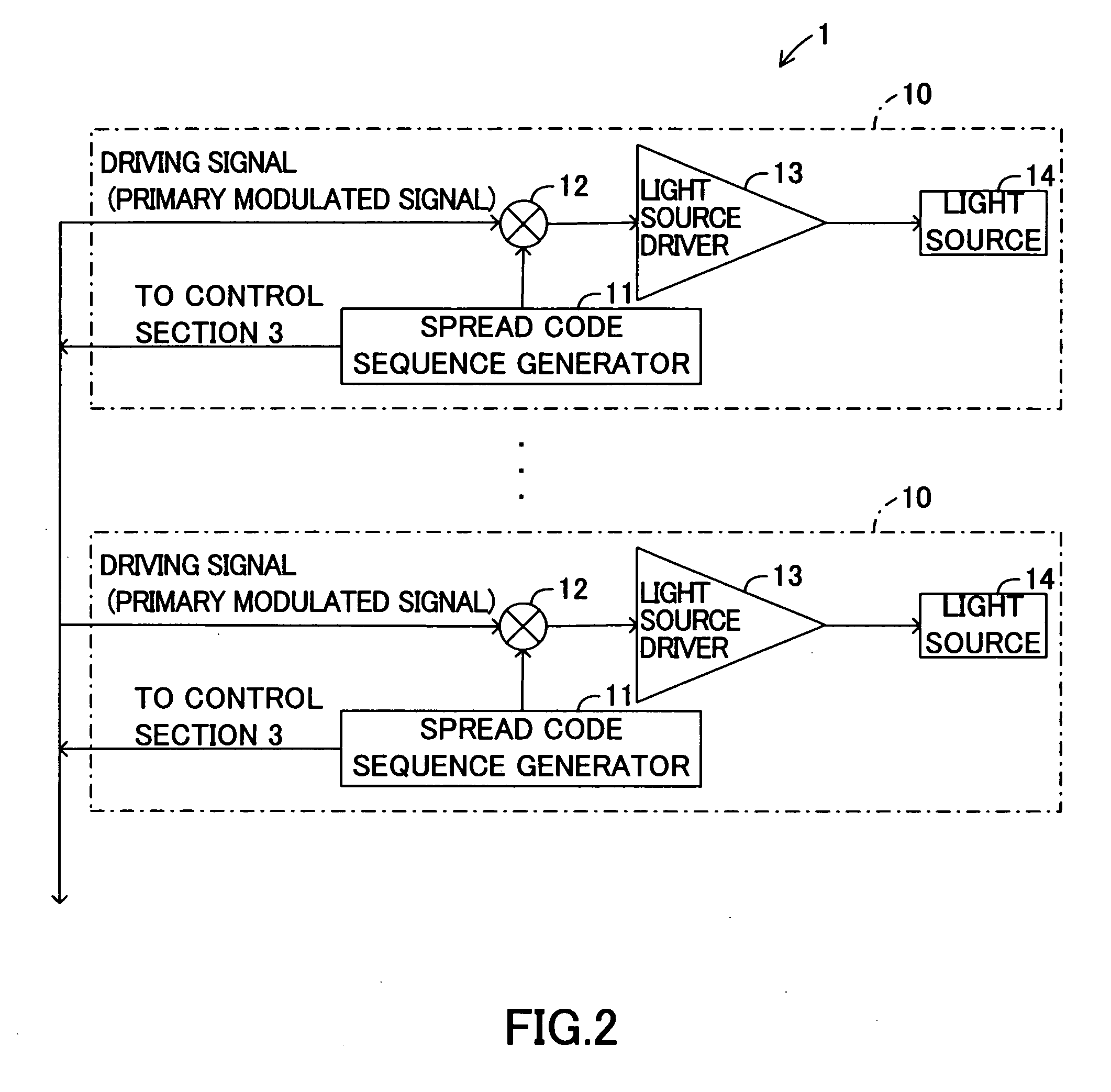
[0016] According to the present invention, the plurality of light emission means can respectively inject a plurality of spectrum modulated light beams having different specific wavelengths into a living organism. The light detection means employs the spread code sequences employed by the light emission means, and thus the light detection means can selectively receive the light beams which have been emitted from the specific light emission means and transmitted through the living organism, can despread an electrical signal corresponding to the light beams, and can detect a signal contained in the light beams. Therefore, even when a number of light emission means are provided, the light detection means can actively avoid adverse effects of light crosstalk or outside light. Since one light detection means can identify and receive light beams emitted from the plurality of light emission means, the number of the light detection means required for measurement can be reduced, and the apparatus per se can be downsized.
[0017] Also, the light detection means can selectively detect light beams having different specific wavelengths emitted from specific light emission means, and can output, for each of the light beams having different specific wavelengths, a signal including information obtained when the light beams are transmitted through the living organism. Therefore, points at which biological information is measured can be densely arranged; i.e., the measurement resolution can be improved considerably, and the control means can measure biological information more accurately and in more detail.
[0019] Since a spread code sequence can be generated by varying the chip frequency, a rapid biological change in a living organism (e.g., nervous activity in a living organism) can also be measured as biological information. Specifically, when a spread code sequence is generated by significantly varying a chip frequency, the bandwidth of light which is emitted from the light emission means on the basis of a spread-spectrum-modulated signal can be increased. When biological information is measured by use of the light of increased bandwidth, a change in the light scattering state associated with such a rapid biological change can be detected. Therefore, when the chip frequency is appropriately varied in accordance with the rate of change in biological information to be measured, the biological information can be measured in a very accurate and detailed manner. In addition, a rapid change occurring in a living organism can be real-time observed by displaying a signal output from the light detection means on, for example, a display apparatus.

Problems solved by technology

However, this apparatus may fail to eliminate adverse effects on measurement caused by, for example, mutual interference (crosstalk) between light beams emitted from the semiconductor laser, or outside light (e.g., light from an inverter-type fluorescent lamp), leading to limited measurement accuracy.
Therefore, a light beam to be received (necessary light beam) is not actively identified, and thus adverse effects of light crosstalk or outside light on measurement may fail to be avoided.
Therefore, the apparatus may become large in size, and multi-channel measurement may become physically difficult.

Method used


Image

  • Biological information measuring apparatus and method for controlling the apparatus
  • Biological information measuring apparatus and method for controlling the apparatus
  • Biological information measuring apparatus and method for controlling the apparatus

Examples


Embodiment Construction

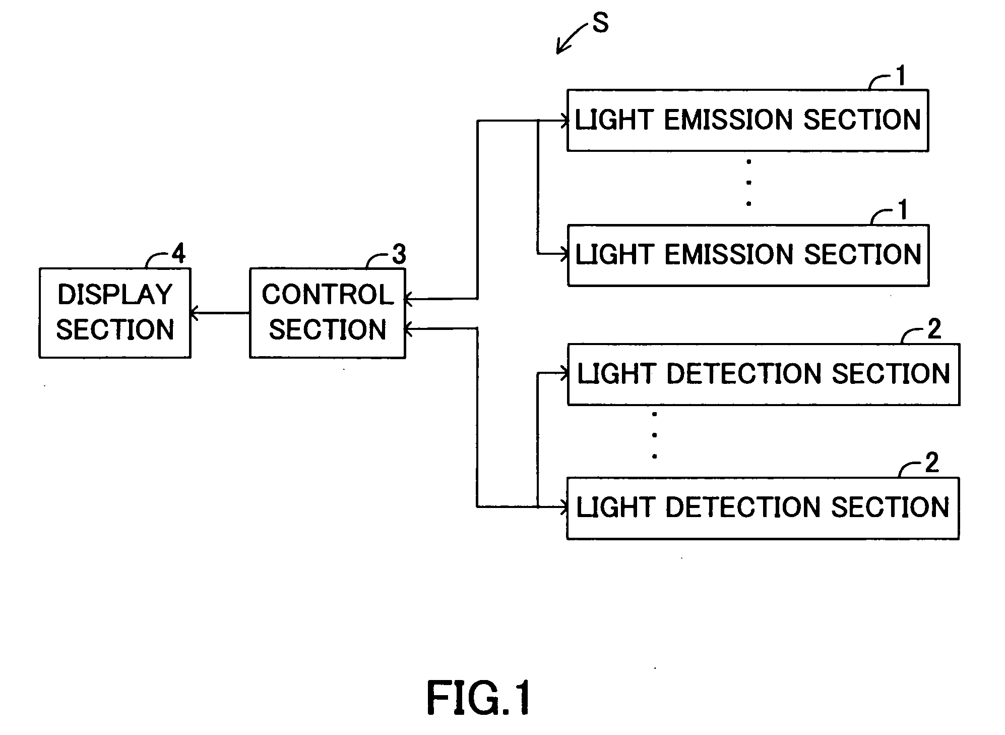
[0030] An embodiment of the present invention will next be described with reference to the drawings. FIG. 1 is a block diagram schematically showing the configuration of a biological information measuring apparatus S according to the present invention. As shown in FIG. 1, the biological information measuring apparatus S includes a plurality of light emission sections 1 which emit light beams having specific wavelengths; and a plurality of light detection sections 2 which detect the light beams which have been emitted from the light emission sections 1 and transmitted through a living organism.

[0031] The light emission sections 1 and the light detection sections 2 are connected to a control section 3. The control section 3 includes, as a main component, a microcomputer including CPU, ROM, RAM, a timer, etc., and totally controls the operation of the biological information measuring apparatus S. The control section 3 calculates biological information (e.g., blood oxygen level in the ...


PUM


Abstract

A biological information measuring apparatus includes a plurality of light emission sections, a plurality of light detection sections, and a control section. Each light emission section injects, into a living organism, a spectrum-modulated light beam having a specific wavelength. The control section acquires a spread code sequence employed by each of the light emission sections for spread spectrum modulation, and supplies the spread code sequence to the light detection sections. By use of the spread code sequence, each light detection section selectively receives a specific reflected light beam having the spread code sequence, which is selected from among the light beams which have been emitted from the light emission sections and reflected in the living organism. Subsequently, each light detection section despreads an electrical signal corresponding to the thus-received reflected light beam, and outputs a detection signal corresponding to the intensity of the reflected light beam.

Description

BACKGROUND OF THE INVENTION [0001] 1. Field of the Invention [0002] The present invention relates to a biological information measuring apparatus for acquiring various types of biological information associated with the metabolism of a living organism, such as biological density, water content, blood oxygen level, glucose level, blood glucose level, and pulse, on the basis of the mechanism that the transmission of light through a living organism necessary signal with wavelength of the light; and to a method for controlling the apparatus. [0003] 2. Background Art [0004] In recent years, there have been actively proposed, as an apparatus and method for conveniently analyzing the interior of a living organism in a noninvasive manner, apparatuses and methods for acquiring information on the interior of a living organism by emitting light from a light source provided on the surface of the living organism to the interior of the organism, and receiving reflected light which has been transm...

Claims


Application Information

Patent Timeline
Patent Type & Authority Applications(United States)
IPC IPC(8): G06K9/00
CPCA61B5/14532A61B5/14553A61B5/4869G01N21/359G01N2201/0691G01N2021/1785G01N2021/3144G01N2021/3148G01N21/4795
Inventor OHASHI, MITSUO
Owner SPECTRATECH
Learn More