Phase-lock loop-based clocking system, methods and apparatus

a clocking system and phase lock technology, applied in the direction of electrical equipment, pulse automatic control, etc., can solve the problems of high noise component of data and images formed from such data, jitter, noise, etc., and achieve the effect of reducing noise in the clock signal

Active Publication Date: 2014-07-22
LIGHTLAB IMAGING
View PDF31 Cites 49 Cited by
  • Summary
  • Abstract
  • Description
  • Claims
  • Application Information

AI Technical Summary

Benefits of technology

[0009]In one aspect, the invention relates to using a phase-locked loop to reduce noise in a clock signal for swept source light sources including Fourier Domain Mode Locked (FDML) lasers.

Problems solved by technology

If the relevant signals are not properly synchronized, data and the images formed from such data can have a high noise component.
Further, in the case of interferometer based modalities, no sample data is generated if interference does not occur, which can result when sweeps of the optical source and other data collection events are not synchronized.
Given the complexity of the OCT systems, errors associated with the clock can result in jitter, noise, and other undesirable effects.

Method used


Image

  • Phase-lock loop-based clocking system, methods and apparatus
  • Phase-lock loop-based clocking system, methods and apparatus
  • Phase-lock loop-based clocking system, methods and apparatus

Examples


Embodiment Construction

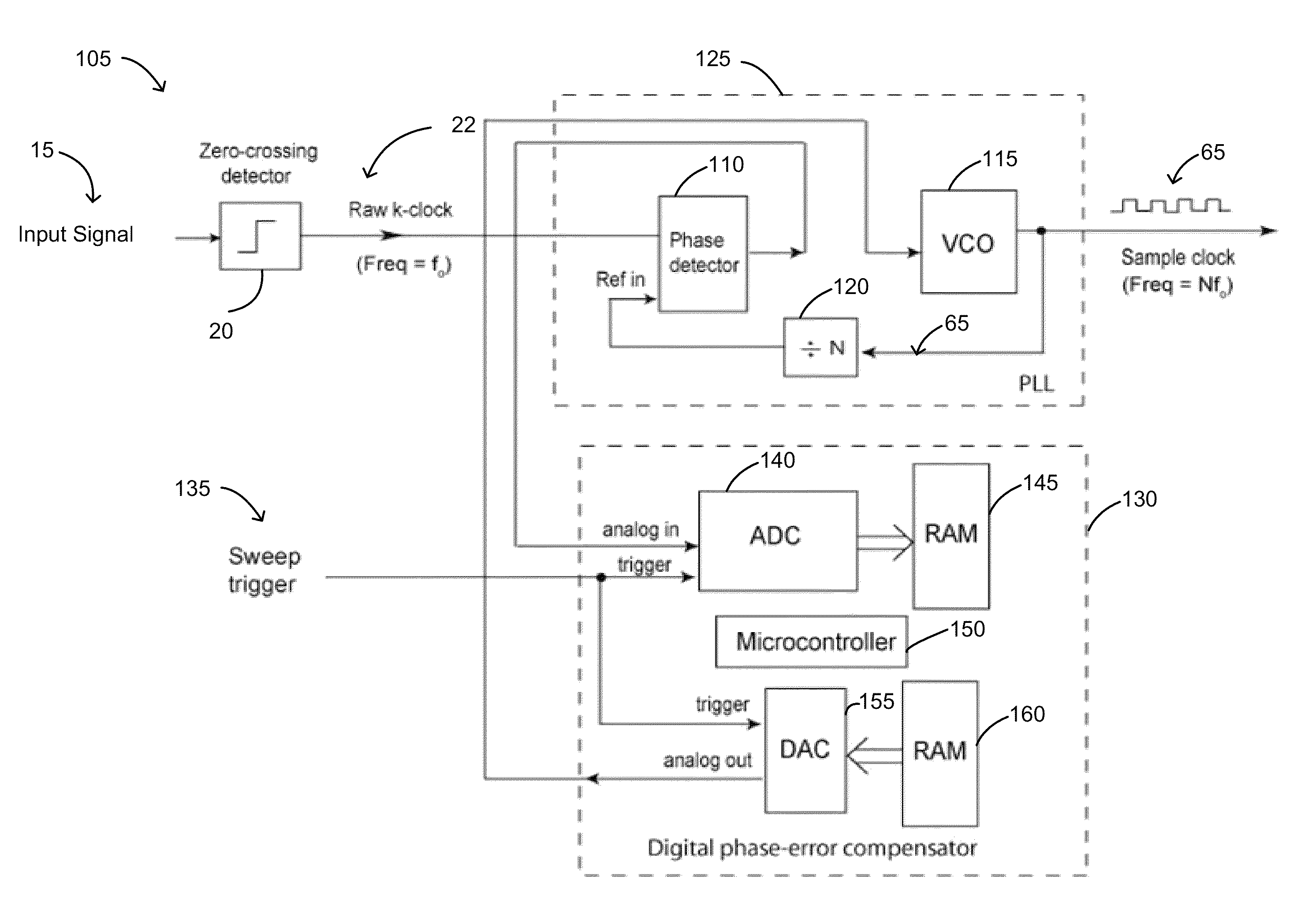
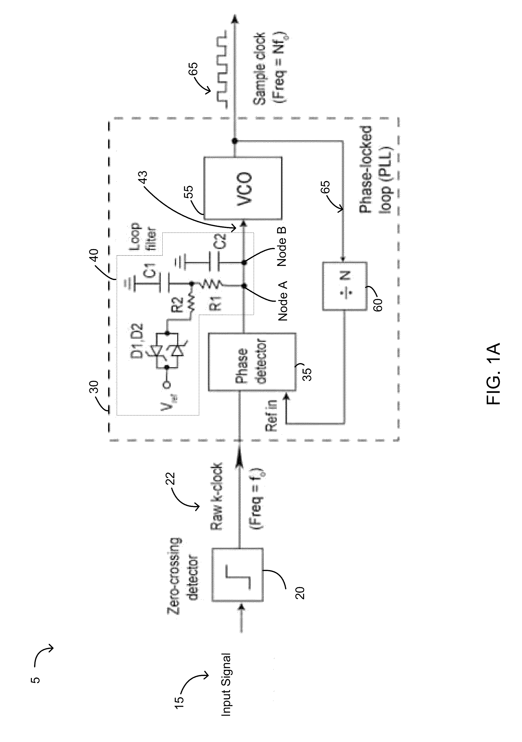
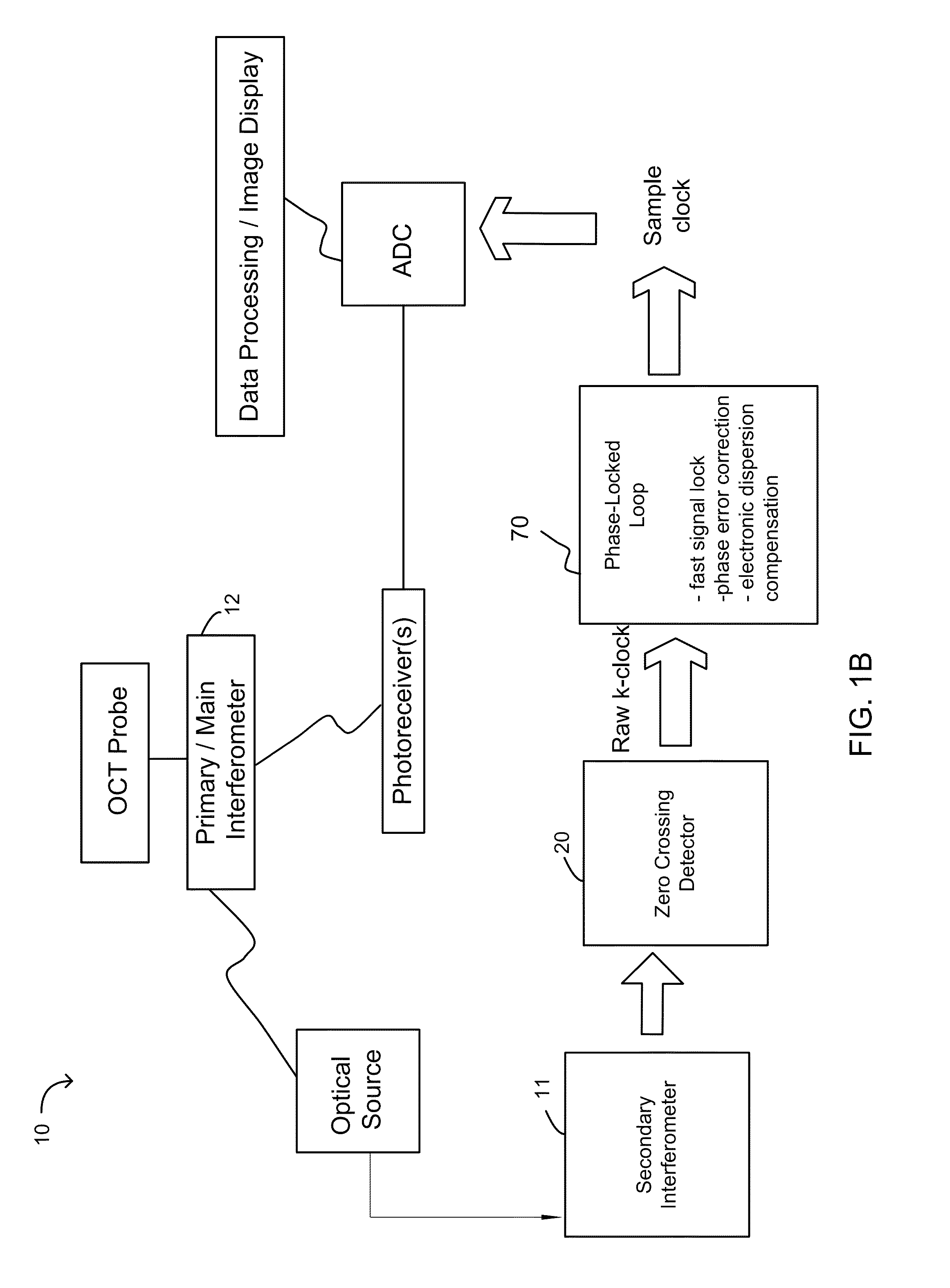
[0029]Swept-source OCT systems (also called frequency-domain or scanning-laser OCT systems) are complex systems that include multiple electrical and optical signals as inputs and outputs. For example, OCT systems can include optical sources, electro-optical converters, interferometers, couplers, probes, clock generators, and other components. The transmission and receipt of optical and electrical elements between such components, as applicable, can result in unwanted noise, jitter, phase changes and other effects. In part, embodiments of the invention employ one or more phase-locked loops (PLLs) to address some of the issues relating to signal clocking and synchronization.

[0030]Specifically, synchronizing data collection and operation of the optical source has particular challenges in OCT. Synchronizing the analog-to-digital conversion of the OCT data signal with the instantaneous optical frequency of the tunable light source using a typical clock generator can lead to unwanted effe...


PUM


Abstract

In part, the invention relates to an optical coherence tomography system that includes one or more phased-locked loop circuits. In one embodiment, the phased-locked loop circuit includes a phase detector, a loop filter, and a voltage controlled oscillator wherein the phased-locked loop circuit is configured to generate a sample clock. The optical coherence tomography system can include an analog to digital converter having a sample clock input, an interferometric signal input, and a sample data output, the analog to digital converter configured to receive the sample clock and sample OCT data in response thereto. In one embodiment, the phased-locked loop circuit is configured to lock on a first signal in less than or equal to about 1 microseconds.

Description

CROSS REFERENCE TO RELATED APPLICATIONS[0001]This application is a continuation of U.S. application Ser. No. 13 / 284,122, filed on Oct. 28, 2011, the entire disclosure of which is incorporated by reference herein.FIELD OF INVENTION[0002]In part, the invention generally relates to devices and methods suitable for synchronizing devices or otherwise generating clock signals or related signals in a data collection or data processing system such as optical coherence tomography systems.BACKGROUND[0003]Various types of imaging modalities such as ultrasound, magnetic resonance imaging, optical coherence tomography (OCT) and others require different signals to be synchronized. This is achieved using various tracking and clocking techniques and devices. If the relevant signals are not properly synchronized, data and the images formed from such data can have a high noise component. Further, in the case of interferometer based modalities, no sample data is generated if interference does not occu...

Claims


Application Information

Patent Timeline
Patent Type & Authority Patents(United States)
IPC IPC(8): H03L7/06
CPCH03L7/07H03L7/0805H03L7/06H03L7/104H03L7/093
Inventor SCHMITT, JOSEPH, M.
Owner LIGHTLAB IMAGING
Why Eureka
Try Eureka