System for synchronizing display of images in a multi-display computer system

a multi-display computer system and image synchronization technology, applied in the direction of pulse technique, static indicating device, instruments, etc., can solve the problems of fixed loop speed, slow loop adaptability, visible distortion,

Inactive Publication Date: 2005-05-05
RPX CORP +1
View PDF8 Cites 45 Cited by
  • Summary
  • Abstract
  • Description
  • Claims
  • Application Information

AI Technical Summary

Benefits of technology

[0017] Another aspect of the invention is the phase-locked loop circuit having a digital rate controller. The digital rate control feat

Problems solved by technology

When the horizontal or vertical synchronization pulses of the video signals generated by the participating processors are not aligned, visible distortions will be apparent.
A drawback to using a conventional phase-locked loop, however, is that the loop speed is fixed.
A slow loop will be slow to adapt when the signals get out of synchronization.
In contrast, a very fast loop will snap the signals into synchronization, often causing visible distort

Method used


Image

  • System for synchronizing display of images in a multi-display computer system
  • System for synchronizing display of images in a multi-display computer system
  • System for synchronizing display of images in a multi-display computer system

Examples


first embodiment

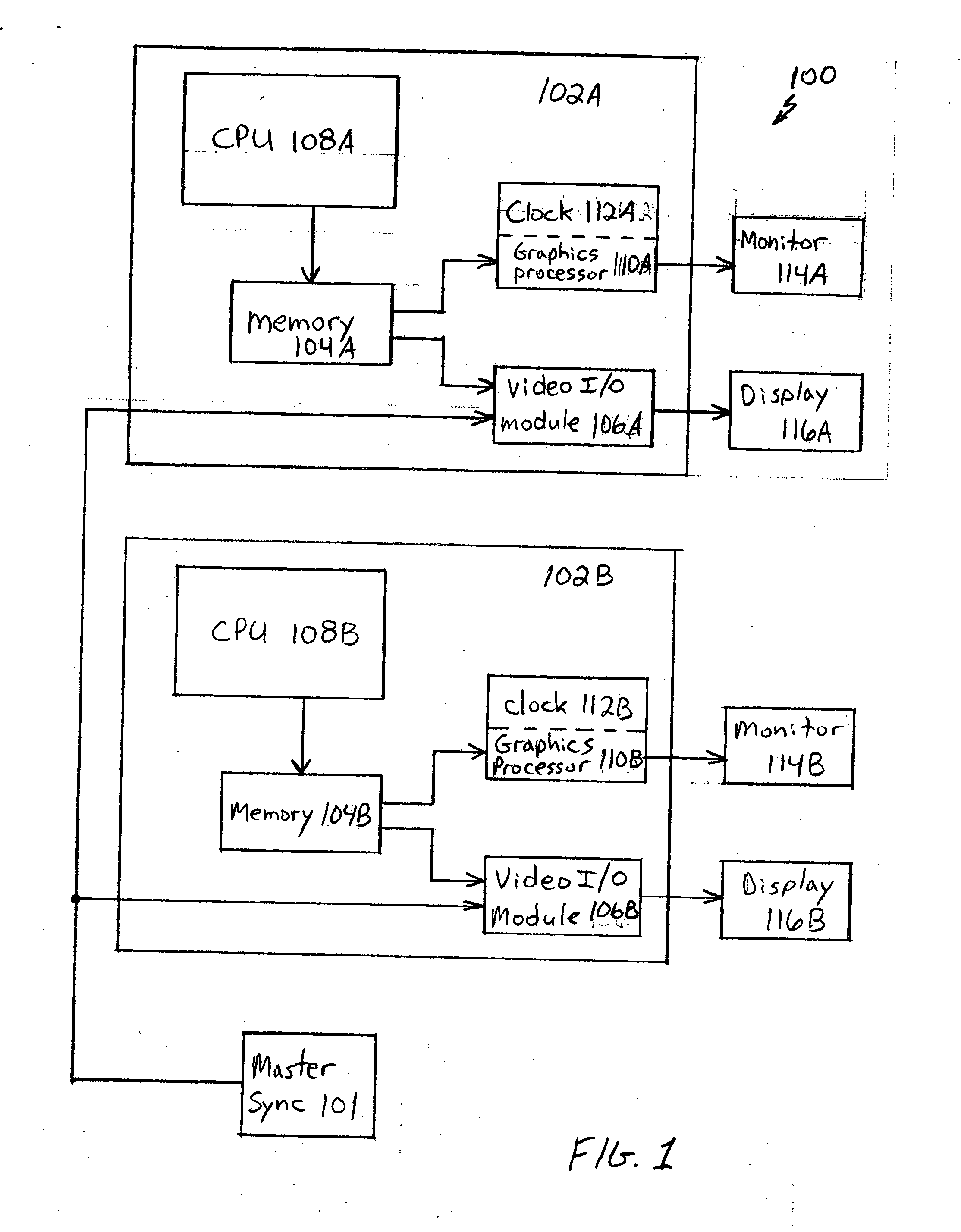
[0029]FIG. 1 is a diagram of a multiple display computer graphics system 100 according to the present invention. The computer graphics system 100 has two or more computer processing systems 102. Two are depicted in this example, but system 100 can contain any number of computer processing systems. In this embodiment, computers 102 are arranged in a flat configuration (i.e., no hierarchical or master / slave type relationship).

[0030] Each computer 102 includes a central processing unit (CPU) 108, memory 104, a graphics processor 110, a monitor 114 and a display 116. Graphics processor 110 includes a clock 112. Each computer 102 also includes a video input / output (I / O) module 106. Graphics processor 110 receives graphics data from memory 104 under control of CPU 108 and displays graphical images on monitor 114. Video I / O module 106 receives video data from memory 104 under control of CPU 108 and displays video images on display 116.

[0031] In an example embodiment, monitor 114 is a cath...

second embodiment

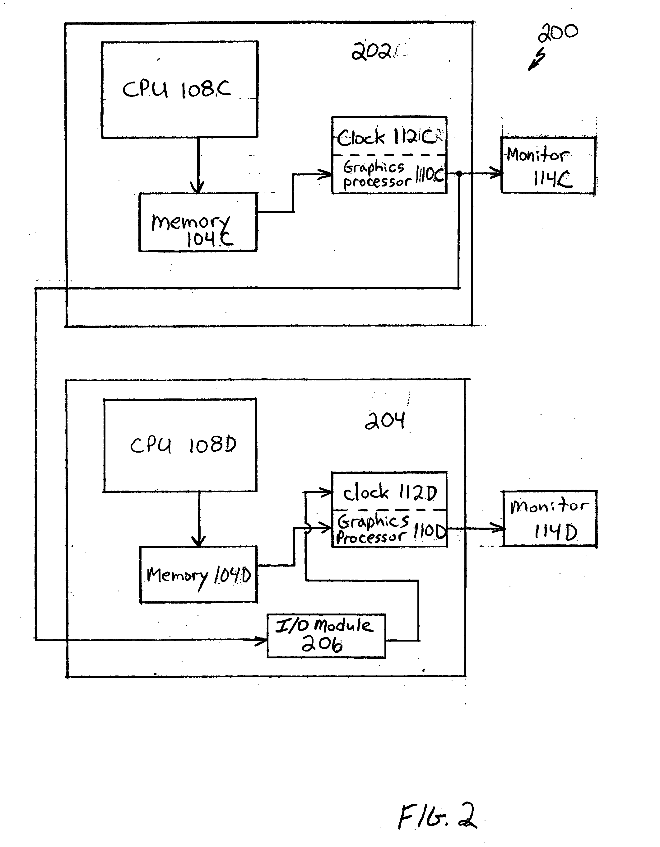
[0041]FIG. 2 is a diagram of a multiple display computer graphics system 200 according to the present invention. Computer graphics system 200 has a master computer processing system 202 and at least one slave computer processing system 204. In this embodiment, computers 202 and 204 are arranged in a hierarchical or master / slave configuration. As with system 100, each computer 202, 204 of system 200 includes a central processing unit (CPU) 108, memory 104, a graphics processor 110, and a monitor 114. Graphics processor 110 includes a clock 112. Computer 204 also includes an input / output (I / O) (graphics sync) module 206. Graphics processor 110 receives graphics data from memory 104 under control of CPU 108 and displays graphical images on monitor 114.

[0042] As would be apparent to a person skilled in the art, graphics processor 110 produces a display signal having a format appropriate for display on monitor 114. The display signal could be in a VGA format, for example. Each graphics p...


PUM


Abstract

An image display system synchronizes the display of images on a plurality of display devices. The system includes a first computer system generating a first signal representing first image data to be displayed on a first display device, a second computer system generating a second signal representing second image data to be displayed on a second display device, and means for synchronizing the first and second image data. The synchronizing means includes a phase-locked loop circuit having a digital rate controller. The digital rate controller allows programmable control of the speed of the phase-locked loop.

Description

BACKGROUND OF THE INVENTION [0001] 1. Field of the Invention [0002] The present invention is directed to synchronizing video and graphics images displayed on multiple display devices. [0003] 2. Related Art [0004] Obtaining visual realism is crucial in computer graphics systems. To this end, it is often necessary to use multiple video or graphics processors to produce multiple levels of images on a single display device (e.g., a CRT, LCD, active matrix or plasma display). In the alternative, some video or graphics systems seek to achieve visual reality by generating a large visual image across multiple display devices. Each processor contributes to the overall image by providing a video or graphics signal representing, for example, either a front, left, or right view of the scene being displayed. Proper synchronization between the signals being provided to the various display devices is key to maintaining the reality of the scene being presented. [0005] Several standards have been es...

Claims


Application Information

Patent Timeline
IPC IPC(8): G06F3/14G09G3/20G09G5/00G09G5/12
CPCG06F3/1423G09G3/2096G09G2360/02G09G5/12G09G5/008
Inventor KENNEDY, JOSEPH P.KLENOSKI, JOHN A.SADOWSKI, GREG
Owner RPX CORP
Why Eureka
Try Eureka