Clock data recovery circuitry and phase locked loop circuitry with dynamically adjustable bandwidths

Inactive Publication Date: 2006-12-12
ALTERA CORP
View PDF15 Cites 49 Cited by
  • Summary
  • Abstract
  • Description
  • Claims
  • Application Information

AI Technical Summary

Benefits of technology

[0011]The CDR circuitry or PLL circuitry can be designed to have a dynamically adjustable bandwidth that does not require the circuitry to be reconfigured in order to reprogram the circuitry with a new bandwidth setting. One CDR circuit or PLL circuit can be provided to support multiple systems or protocols, multiple parameter requirements for a given system or protocol, and changes in the input frequency or data rate within a given system or protocol. Providing CDR circuitry or PLL circuitry with a dynamically adjustable bandwidth allows for the flexibility to change the bandwidth while the circuitry

Problems solved by technology

Such custom protocols often have at least some features similar to industry

Method used


Image

  • Clock data recovery circuitry and phase locked loop circuitry with dynamically adjustable bandwidths
  • Clock data recovery circuitry and phase locked loop circuitry with dynamically adjustable bandwidths
  • Clock data recovery circuitry and phase locked loop circuitry with dynamically adjustable bandwidths

Examples


Embodiment Construction

[0019]The invention is described herein primarily in the context of clock data recovery (CDR) circuitry for clarity, although the invention can also be applied to phase locked loop (PLL) circuitry both as part of the CDR circuitry or separate from the CDR circuitry. The PLL circuitry can be used alongside CDR circuitry on a programmable logic device (PLD) or on a PLD that does not have CDR circuitry,

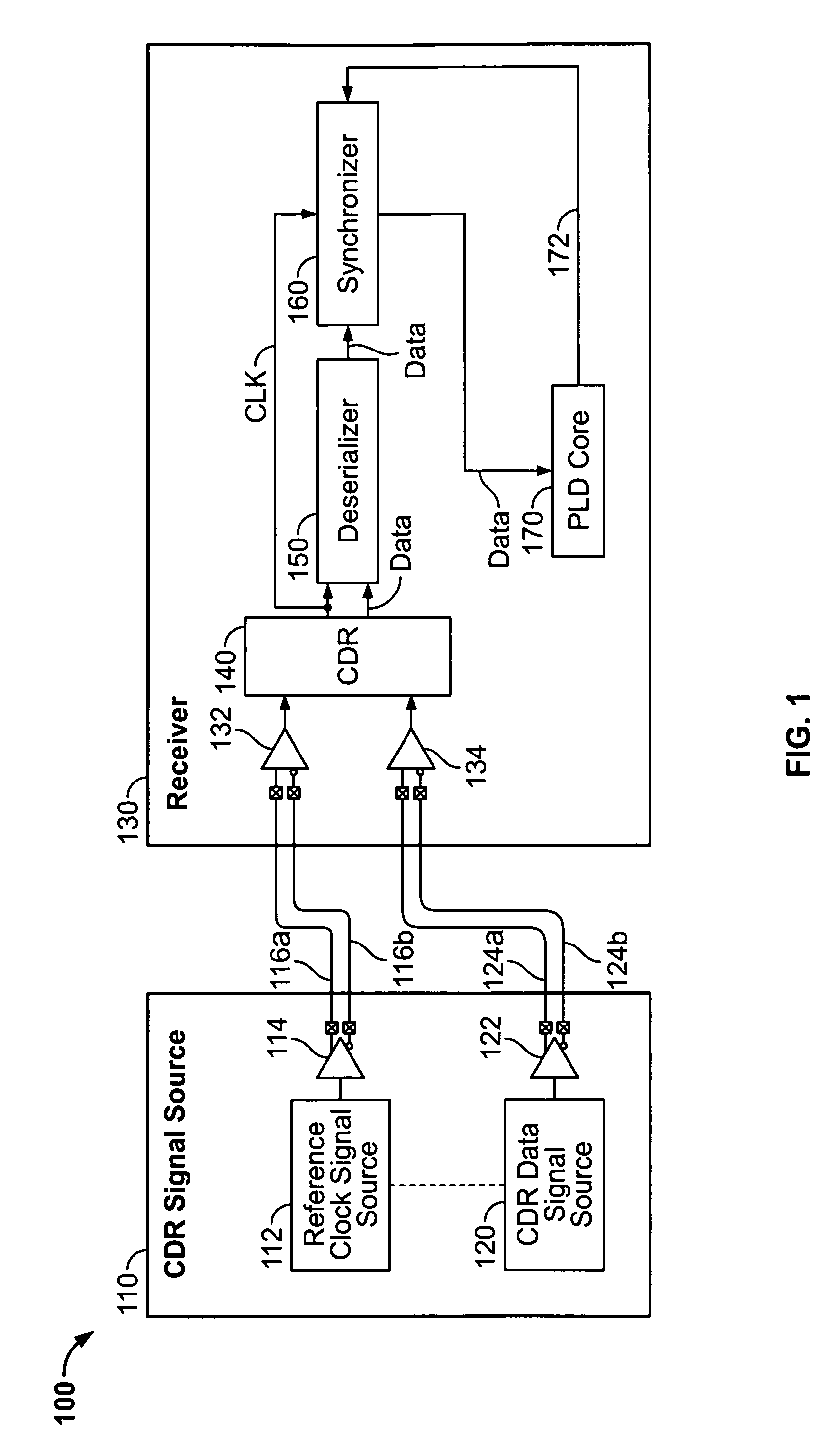
[0020]FIG. 1 shows an illustrative embodiment of CDR signaling apparatus 100 in accordance with the invention. This apparatus includes a CDR signal source 110 and a receiver 130. Although elements 110 and 130 could be on the same integrated circuit, that is generally not the case and they are more typically portions of separate integrated circuits or circuit assemblies. For example, in systems like those shown in FIG. 5, receiver 130 could be part of element 510 / 520, while source 110 could be part of any other element(s) 530, 540, 550, and / or 560.

[0021]CDR signal source 110 includes a re...


PUM


Abstract

Clock data recovery (CDR) circuitry or phase locked loop (PLL) circuitry can be provided with a dynamically adjustable bandwidth. One CDR circuit or PLL circuit can be provided to support multiple systems or protocols, multiple parameter requirements for a given system or protocol, and changes in the input frequency or data rate within a given system or protocol. The parameters can include jitter (e.g., jitter tolerance, jitter transfer, jitter generation), source of dominant noise, and lock time. Control signals can be used to dynamically adjust the bandwidth of the CDR circuitry or PLL circuitry while the circuitry is processing data. The control signals can be set by a PLD, by a processor, by circuitry external to the PLD, or by user input.

Description

BACKGROUND OF THE INVENTION[0001]This invention relates to clock data recovery circuitry and phase locked loop circuitry. More particularly, this invention relates to providing clock data recovery circuitry and phase locked loop circuitry with dynamically adjustable bandwidths.[0002]An increasingly important type of signaling between devices is signaling in which the clock signal information is embedded in a serial data stream so that no separate clock signal needs to be transmitted. For example, data may be transmitted serially in “packets” of several successive serial data words preceded by a serial “header” that includes several training bits having a predetermined pattern of binary ones and zeros. The clock signal information is embedded in the data signal by the high-to-low and / or low-to-high transitions in that signal, which must have at least one high-to-low or low-to-high transition within a certain number of clock signal cycles. At the receiver the clock signal is “recovere...

Claims


Application Information

Patent Timeline
IPC IPC(8): G06F1/04G06F1/06G06F1/08G06F1/24
CPCH03L7/087H03L7/107H03L7/18H04L7/0008H04L7/033H03L7/1072
Inventor ASADUZZAMAN, KAZIWONG, WILSONSHUMARAYEV, SERGEY
Owner ALTERA CORP
Why Eureka
Try Eureka