Retaining Device for a Linear Transmission System
- Summary
- Abstract
- Description
- Claims
- Application Information
AI Technical Summary
Benefits of technology
Problems solved by technology
Method used
Image
Examples
Embodiment Construction
[0023]The present invention will be more clear from the following description when viewed together with the accompanying drawings, which show, for purpose of illustrations only, the preferred embodiment in accordance with the present invention.
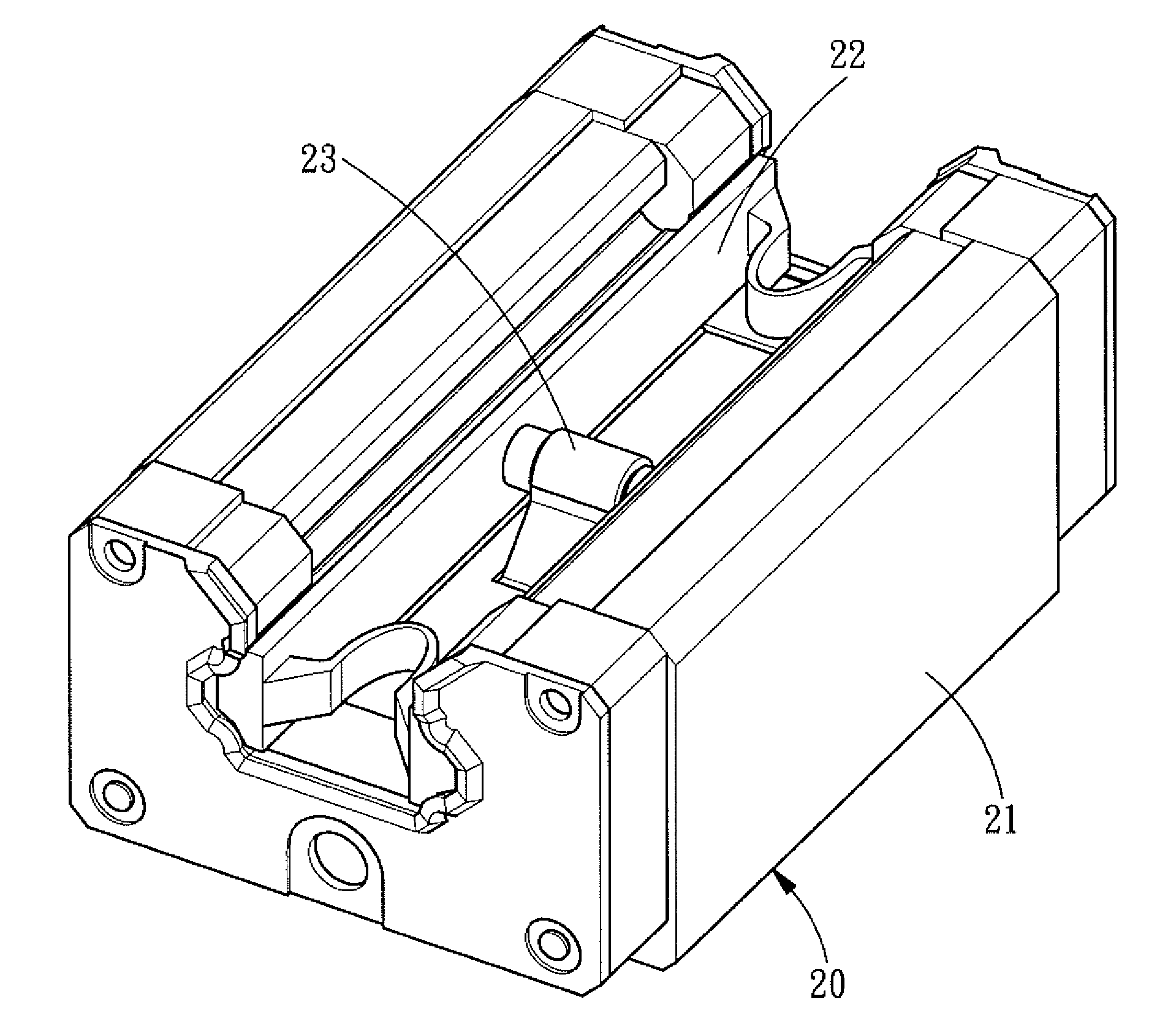
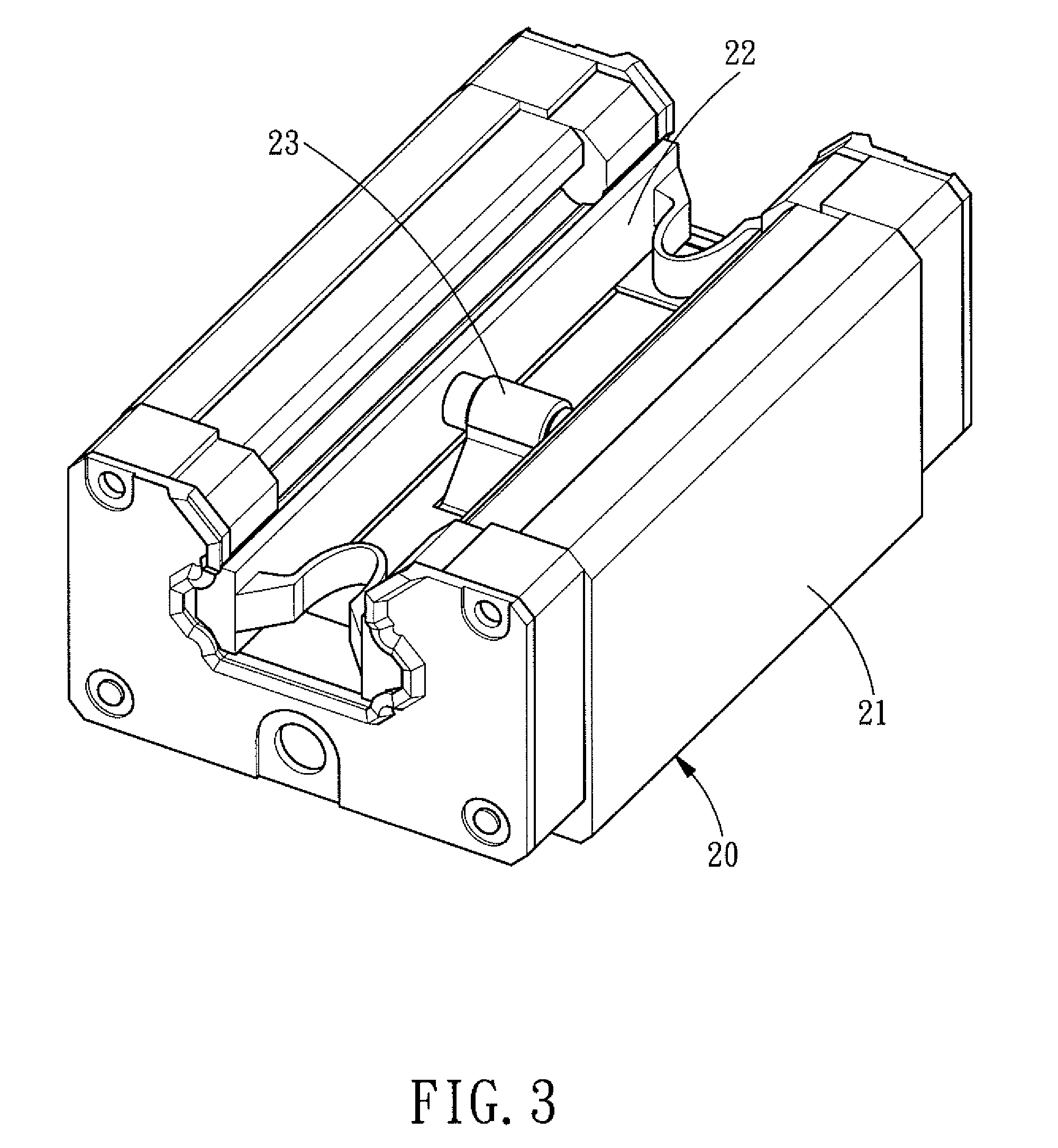
[0024]Referring to FIGS. 3 and 4, a retaining device 20 for a linear transmission system comprises: a sliding block 21, a rail clamp 22, and a spring fastener 23.
[0025]The sliding block 21 includes a base 211, an upper retainer 212, two mid retainers 213, two lower retainers 214, and a plurality of rolling elements 215. The base 211 is a U-shaped structure in cross section and has an upper connecting surface 2111, two mid connecting surfaces 2112, and two lower connecting surfaces 2113. The upper retainer 212 is disposed on the upper connecting surface 2111 of the base 211, and a rectangular positioning hole 2121 is formed in the upper retainer 212. The two mid retainers 213 are disposed on the two mid connecting surfaces 2112 of the base 211,...
PUM
 Abstract
Description
Claims
Application Information
 - R&D
- Intellectual Property
- Life Sciences
- Materials
- Tech Scout
- Unparalleled Data Quality
- Higher Quality Content
- 60% Fewer Hallucinations
Browse by: Latest US Patents, China's latest patents, Technical Efficacy Thesaurus, Application Domain, Technology Topic, Popular Technical Reports.
© 2025 PatSnap. All rights reserved.Legal|Privacy policy|Modern Slavery Act Transparency Statement|Sitemap|About US| Contact US: help@patsnap.com


