Efficient detector soft belt forming welding jig

A technology of detectors and soft belts, which is applied in the field of high-efficiency detector soft belt forming welding fixtures, can solve problems such as poor consistency of soft belts, low positioning accuracy, and impact on accuracy, and achieve high-efficiency and high-efficiency soft belt welding, disassembly and assembly The process is simple and the effect of improving the accuracy of welding

Active Publication Date: 2016-02-17
WUHAN TELECOMM DEVICES
View PDF8 Cites 6 Cited by
  • Summary
  • Abstract
  • Description
  • Claims
  • Application Information

AI Technical Summary

Problems solved by technology

In the Chinese patent with the patent number ZL201010262437, the soft belt of the shrapnel fixture needs to be moved with tweezers. If the positioning is not accurate, the shrapnel needs to be loosened and clamped. Repeated operations are time-consuming, the positioning accuracy is not high, and there is a hidden danger of false welding.
[0005] In the past, the soft strip welding fixture usually divides the soft strip forming and the positioning and clamping of the soft strip into two processes. The consistency of the soft strip after forming is not good, and secondary clamping is required, which affects the accuracy and low efficiency.

Method used


Image

  • Efficient detector soft belt forming welding jig
  • Efficient detector soft belt forming welding jig
  • Efficient detector soft belt forming welding jig

Examples


Embodiment Construction

[0024] The present invention will be described in further detail below in conjunction with specific embodiments and accompanying drawings. Examples of the described embodiments are shown in the drawings, wherein like or similar reference numerals designate like or similar elements or elements having the same or similar functions throughout. The embodiments described below with reference to the accompanying drawings are exemplary, and are only used to explain the technical solution of the present invention, and should not be construed as limiting the present invention.

[0025] In the description of the present invention, the terms "inner", "outer", "longitudinal", "transverse", "upper", "lower", "top", "bottom" or "front", "rear", "left ", "right" and other indicated orientations or positional relationships are based on the orientations or positional relationships shown in the drawings, and are only for the convenience of describing the present invention and do not require tha...


PUM


Abstract

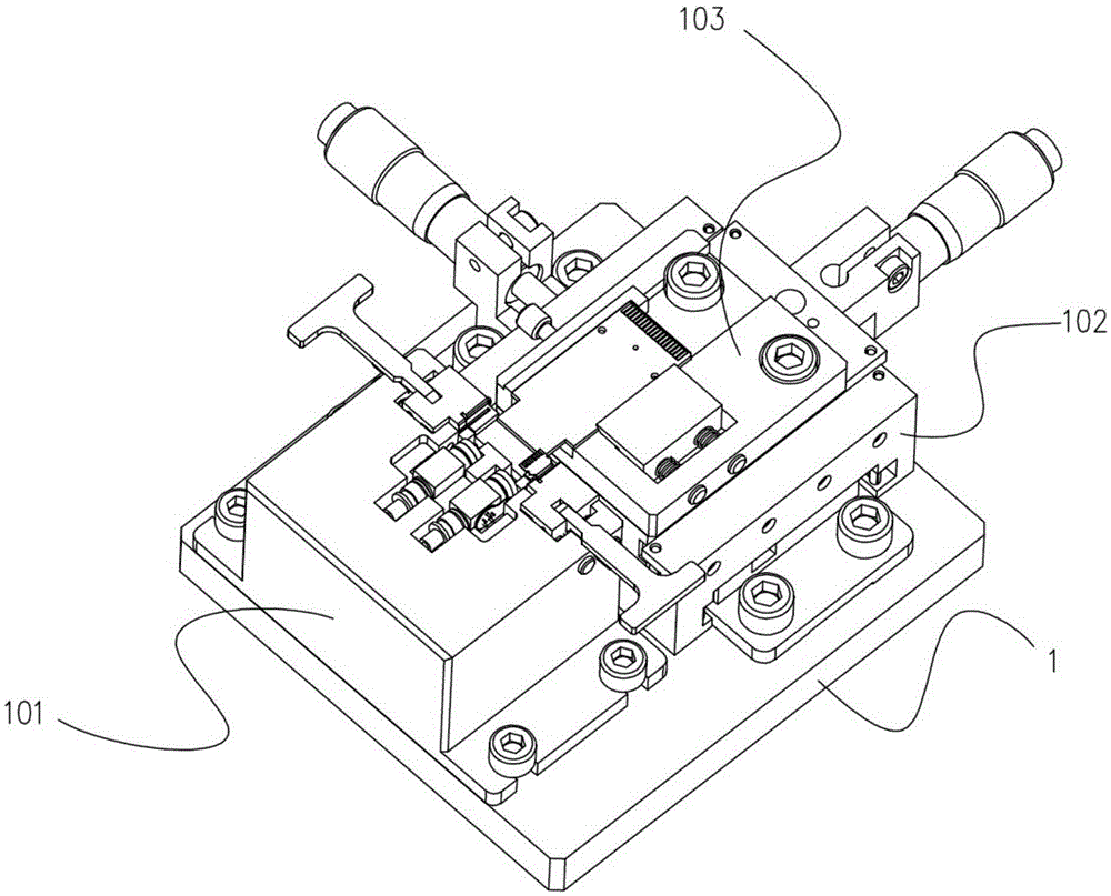
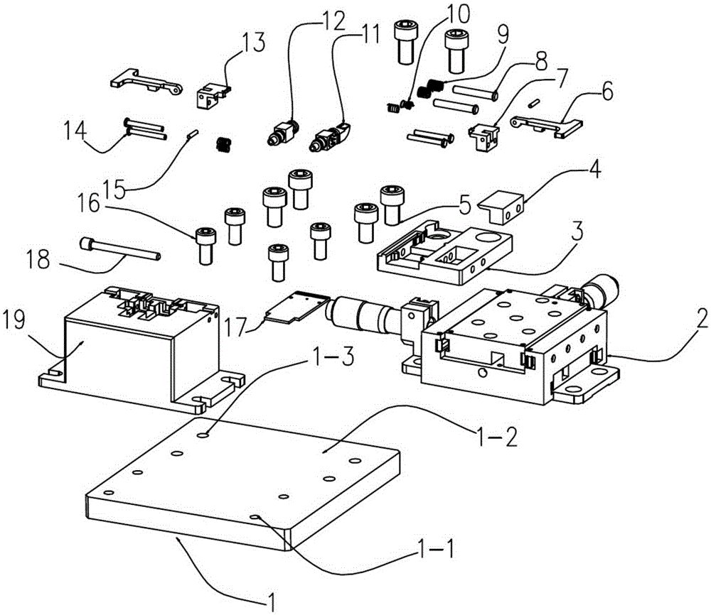
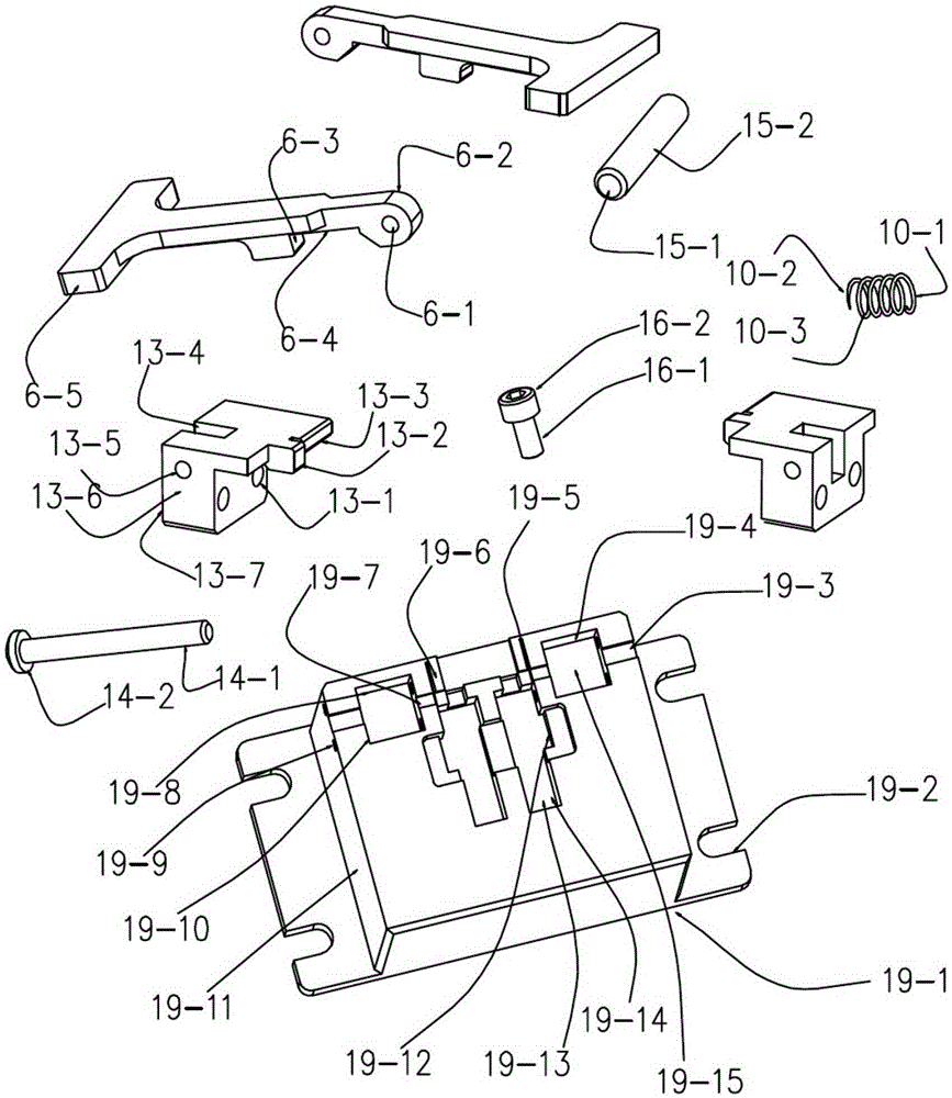
The invention discloses an efficient detector soft belt forming welding jig. The efficient detector soft belt forming welding jig comprises a soft belt positioning mechanism, a fine adjustment alignment mechanism and a printed circuit board (PCB) clamping mechanism which are disposed on a bottom plate, wherein the soft belt positioning mechanism is fixed to a plane of the front side of the bottom plate through small screws and comprises a base which is provided with a positioning groove; the positioning groove can clamp a bi-directional optical sub-assembly (BOSA) device; the fine adjustment alignment mechanism can achieve front-back and right-left displacement through fine adjustment and is fixed to a plane of the rear side of the bottom plate through large screws relative to the soft belt positioning mechanism; the PCB clamping mechanism is disposed on the upper surface of the fine adjustment alignment mechanism and comprises a fixing block and a clamping block; the fixing block is provided with a positioning surface and a boss surface for clamping a PCB; the clamping block is provided with an inclined pressing surface and a stepped stand and can cooperate with the fixing block to clamp the PCB on the PCB clamping mechanism. By means of the structure, accurate alignment and convenient welding of the BOSA device clamped on the base are achieved, and effects of convenient and fast welding and improvement of product yield are also achieved.

Description

technical field [0001] The invention provides a high-efficiency detector flexible belt forming welding jig, especially a detector soft belt welding jig for an optical communication device BOSA. Background technique [0002] The rapid development of the optical communication industry has driven the replacement of optical modules. 40G and 100G products are gradually occupying a dominant position. The mass production of optical modules is becoming larger and larger. The welding process of soft ribbons in assembly production is difficult, which directly restricts product quality and production efficiency. The performance and reliability of optical transceiver products. [0003] Optical module devices take BOSA devices as an example. The flexible strips are usually divided into laser flexible strips and detector flexible strips. The welding process is divided into forming, clamping, alignment, and welding. The soft belt connects the optical device and the integrated circuit to r...

Claims


Application Information

Patent Timeline
Patent Type & Authority Applications(China)
IPC IPC(8): B23K37/04B23K37/047
CPCB23K37/0443B23K37/047B23K2101/36
Inventor 梅凯全本庆江毅
Owner WUHAN TELECOMM DEVICES
Why Eureka
Try Eureka