
Method for cutting tempered glass, preparatory structure used in cutting tempered glass, and glass block cut from tempered glass substrate

a technology of tempered glass and cutting method, which is applied in the direction of manufacturing tools, cellulosic plastic layered products, transportation and packaging, etc., can solve the problems of increasing fabrication time and cost, low production yield, and complicating fabrication processes, and achieve the effect of improving the yield rate of cutting tempered glass

Inactive Publication Date: 2012-03-15
WINTEK CHINA TECH LTD +1
View PDF3 Cites 81 Cited by
  • Summary
  • Abstract
  • Description
  • Claims
  • Application Information

AI Technical Summary

Benefits of technology

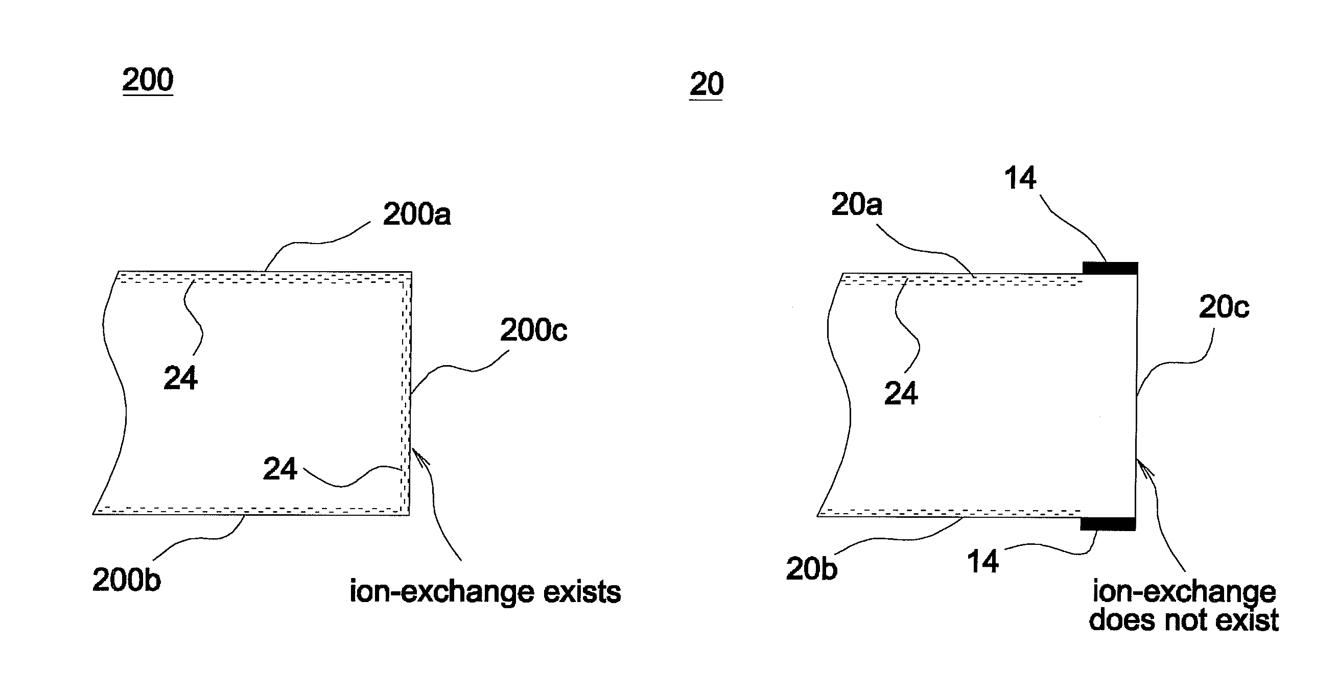
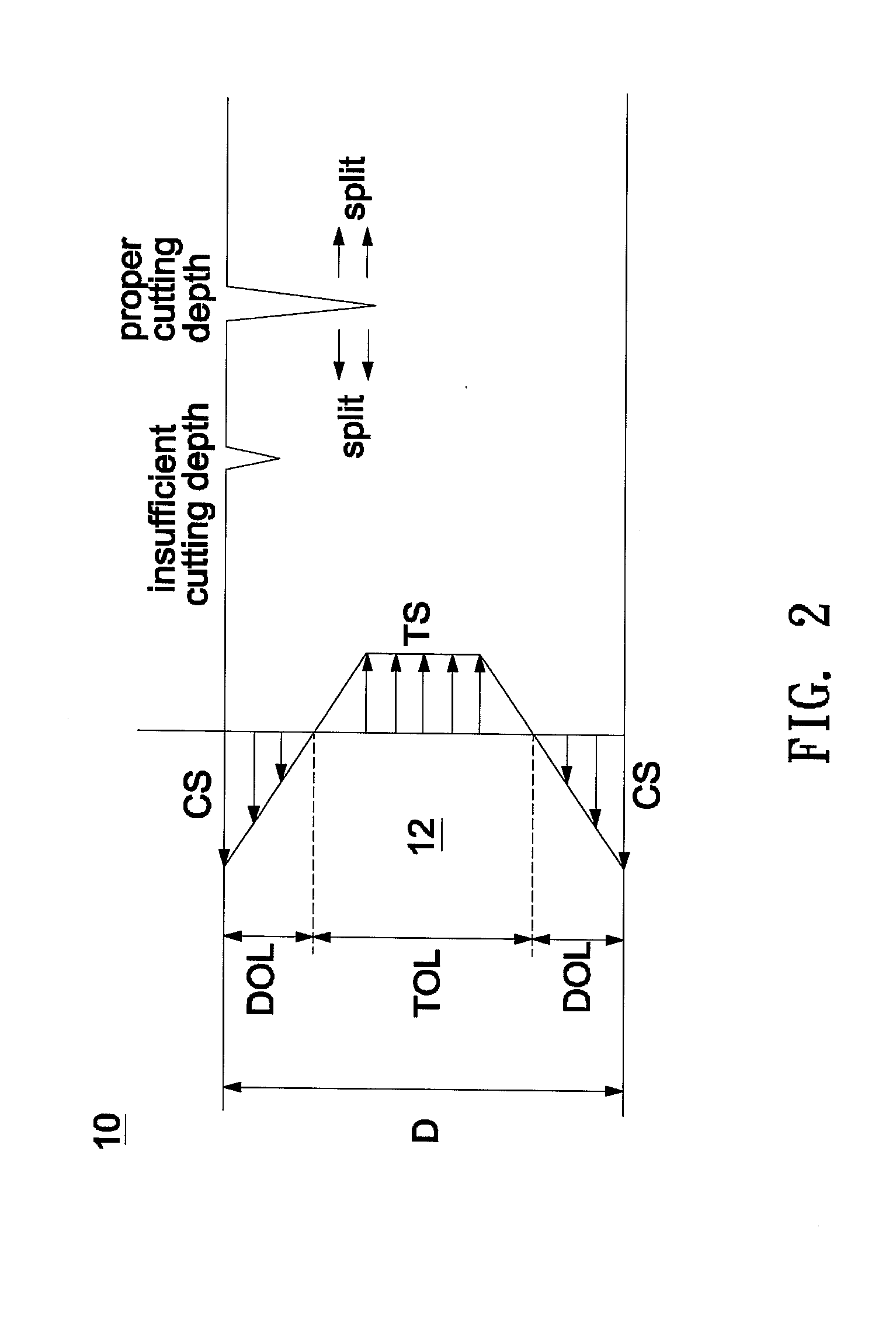
"The invention provides a method for cutting tempered glass with a higher yield rate. This is achieved by using a shielding layer on a part of the surface of the glass substrate where a predetermined cutting path passes through. The shielding layer blocks the formation of ion-exchange on the surface, reducing internal tensile stress and improving the production yield of the tempered glass block. The method also allows for a simplified fabrication process and reduces fabrication time and costs. Additionally, the invention provides a preparatory structure and a glass block cut from tempered glass substrate with a smooth facet and improved yield rate."

Problems solved by technology

This may result in extremely low production yields.
In other words, each of the glass blocks cut from a mother glass substrate needs to be chemically strengthened one after one to thus complicate fabrication processes and increase fabrication time and costs.
However, the mother glass fabrication process is hard to carry out currently, because a mother glass substrate given an ion-exchange strengthening treatment is liable to split during cutting to result in extremely low production yields.

Method used


Image

  • Method for cutting tempered glass, preparatory structure used in cutting tempered glass, and glass block cut from tempered glass substrate
  • Method for cutting tempered glass, preparatory structure used in cutting tempered glass, and glass block cut from tempered glass substrate
  • Method for cutting tempered glass, preparatory structure used in cutting tempered glass, and glass block cut from tempered glass substrate

Examples


Embodiment Construction

[0027]In the following detailed description of the preferred embodiments, reference is made to the accompanying drawings which form a part hereof, and in which are shown by way of illustration specific embodiments in which the invention may be practiced. In this regard, directional terminology, such as “top,”“bottom,”“front,”“back,” etc., is used with reference to the orientation of the Figure(s) being described. The components of the invention can be positioned in a number of different orientations. As such, the directional terminology is used for purposes of illustration and is in no way limiting. On the other hand, the drawings are only schematic and the sizes of components may be exaggerated for clarity. It is to be understood that other embodiments may be utilized and structural changes may be made without departing from the scope of the invention. Also, it is to be understood that the phraseology and terminology used herein are for the purpose of description and should not be ...


PUM

PropertyMeasurementUnit
transparentaaaaaaaaaa
structureaaaaaaaaaa
compression stressaaaaaaaaaa

Abstract

A method for cutting a tempered glass includes the following steps. First, a shielding layer is formed on a part of a surface of a glass substrate, and a predetermined cutting path passes through the part of the surface. Then, a glass substrate is given an ion-exchange strengthening treatment, and the part of the surface covered by the shielding layer substantially does not undergo ion-exchange. Finally, the glass substrate is cut along the predetermined cutting path.

Description

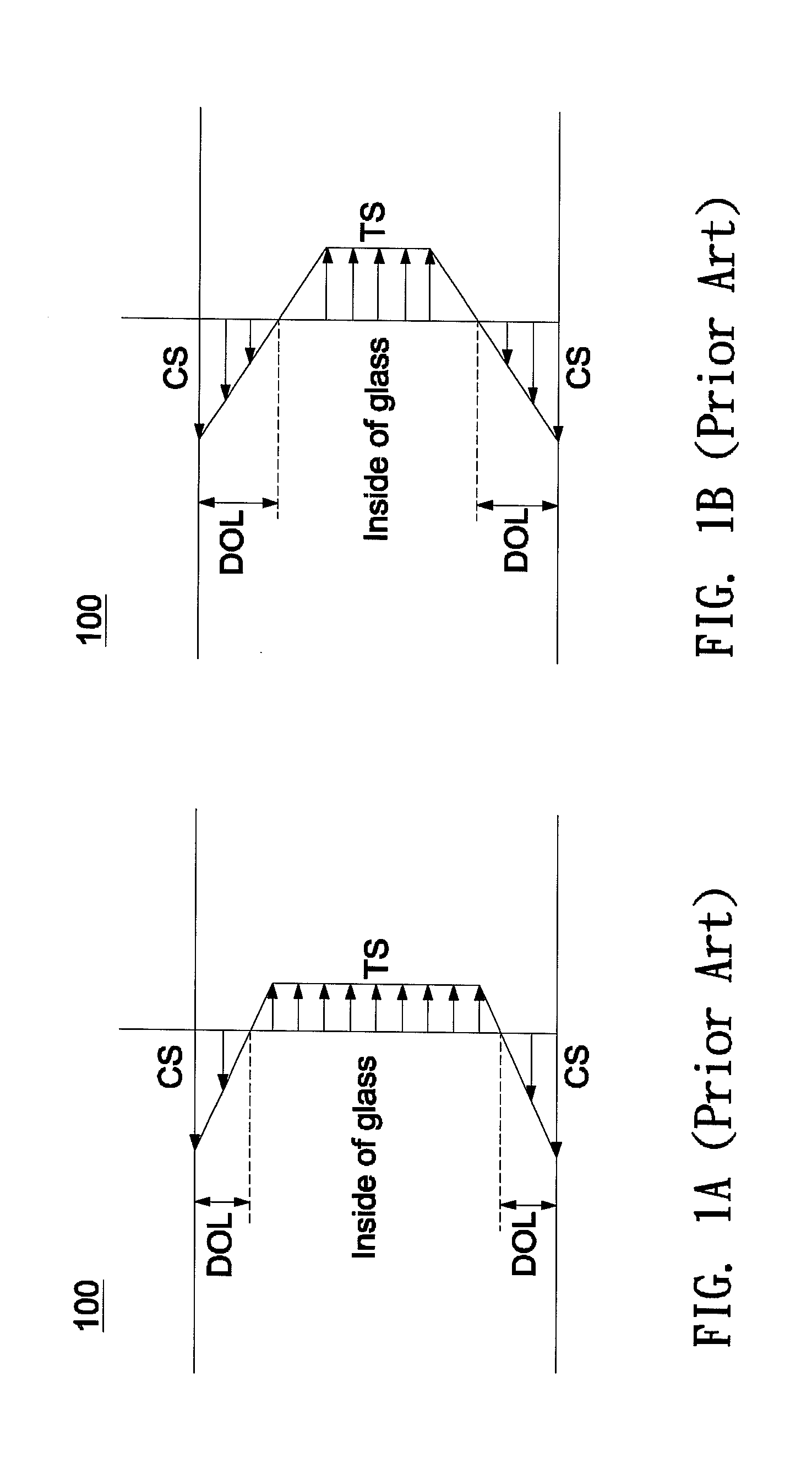
BACKGROUND OF THE INVENTION[0001]a. Field of the Invention[0002]The invention relates to a method for cutting a tempered glass, a preparatory glass structure used in cutting a tempered glass, and a glass block cut from a tempered glass substrate.[0003]b. Description of the Related Art[0004]Generally, conventional methods for strengthening glass mainly include a heat strengthening treatment and a chemically strengthening treatment. For example, in a typical chemically strengthening treatment such as an ion-exchange strengthening treatment, a glass substrate is submersed in a bath containing a potassium salt. This causes sodium ions on the glass surface to be replaced by potassium ions from the bath solution. Under the circumstance, a thin compression stress layer is formed on the skin of the glass substrate. As shown in FIG. 1A and FIG. 1B, a tensile stress TS is formed correspondingly inside a tempered glass 100 to compensate the compression stress CS of a compression stress layer D...

Claims


Application Information

Patent Timeline
Patent Type & Authority Applications(United States)
IPC IPC(8): C03B33/02C03C25/00B32B17/00C03C21/00
CPCC03B33/074C03C17/22Y10T428/24926C03C2218/34Y10T428/24777C03C21/00Y02P40/57
Inventor KANG, HEN-TAHUNG, JENG-JYECHEN, YUNG-LIN
Owner WINTEK CHINA TECH LTD
Learn More