Optical disc having uniform structure

a technology of optical discs and uniform structures, applied in the field of optical discs, can solve the problems of poor recording/reproduction efficiency, poor reproduction compatibility of conventional dvd-rams, and inability to obtain reliable pit signals, so as to improve recording/reproducing capacity, reduce manufacturing costs, and improve yield

Inactive Publication Date: 2006-06-20
SAMSUNG ELECTRONICS CO LTD
View PDF7 Cites 81 Cited by
  • Summary
  • Abstract
  • Description
  • Claims
  • Application Information

AI Technical Summary

Benefits of technology

[0022]Accordingly, it is an object of the present invention to provide an optical disc with an improved yield, a reduced manufacturing cost and an improved recording / reproducing capacity, by forming grooves in both a lead-in area and a lead-out area so as to have the same manufacturing conditions for discs during mastering.
[0023]It is another object of the present invention to provide an optical disc having an improved structure of multiple recording layers such that light power is uniformly irradiated to the multi-layered disc during recording / reproducing.

Problems solved by technology

First, while a DVD-RW having the same physical recording structure as a DVD-ROM (read only disc) has an excellent reproduction compatibility in DVD-ROM drives or DVD players, a DVD-RAM having a phase difference corresponding to depths of a land and a groove requires hardware modification to suitably track lands and grooves. Therefore, a conventional DVD-RAM has a poor reproduction compatibility.
Second, in the context of recording / reproduction characteristics or injection-molding characteristics in recording data on a groove, the grooves formed in a DVD-RW are two or more times shallower than that in a DVD-RAM. Here, if necessary, read only data is formed on the lead-in area 10 in a form of pits 15.
Therefore, a reliable pit signal cannot be obtained where read only data as shallow as a groove depth of a DVD-RW is formed in a DVD-RAM.
Therefore, the groove portion with marks adversely affects the recording power as the data is written on the second recording layer L1 of the dual-layered optical disc, resulting in a poor recording / reproduction efficiency.
However, the problem with a dual recording layer disc is that a difference in light power becomes more serious as the NA increases.
This makes the manufacturing process complex, resulting in a poor yield and an increased manufacturing cost.

Method used


Image

  • Optical disc having uniform structure
  • Optical disc having uniform structure
  • Optical disc having uniform structure

Examples


Embodiment Construction

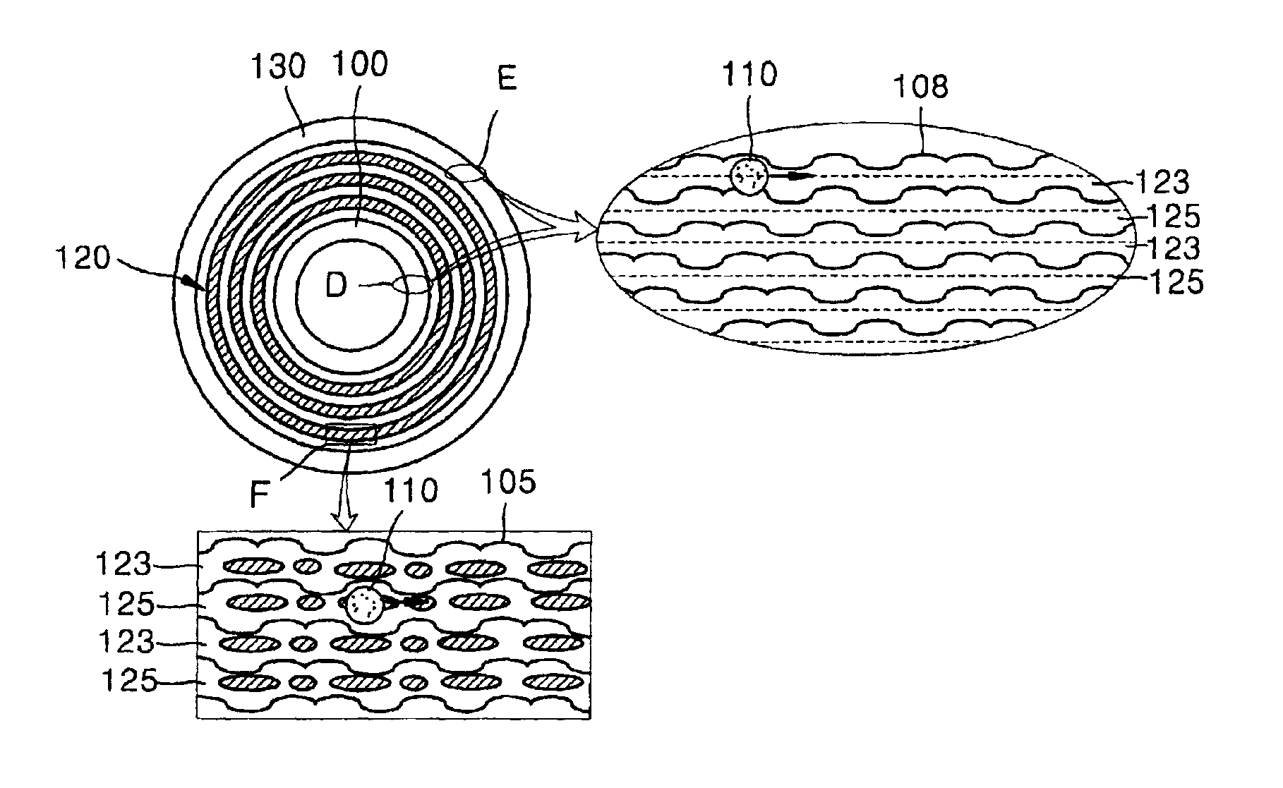
[0053]FIG. 5 shows an optical disc according to an embodiment of the present invention. The optical disc includes a lead-in area 100, a user data area 120 and a lead-out area 130, and grooves 123 and lands 125 that are formed on the entire surface thereof. User data can be recorded on only the grooves 123 or on both the grooves 123 and the lands 125. Where read only data is recorded, waveforms of wobble signals 105 are consecutively recorded on at least one side of the grooves 123 and lands 125, instead of pits.

[0054]An enlarged view of portions D and E shows that the grooves 123 and the lands 125 are alternately formed in the lead-in and lead-out areas 100 and 130, and waveform wobble signals 108 are formed on both the grooves 123 and the lands 125. A portion F shows that the grooves 123 and the lands 125 are alternately formed in the user data area 120, and the wobble signals 105 are formed on both the grooves 123 and the lands 125. Recording and / or reproduction are performed whil...


PUM

PropertyMeasurementUnit
areaaaaaaaaaaa
frequencyaaaaaaaaaa
phaseaaaaaaaaaa

Abstract

An optical disc is manufactured under a uniform condition by forming grooves and lands on the entire surface of the disc. The optical disc is configured to obtain a reliable reproduction signal, and the grooves and lands are formed on a lead-in area, a user data area and a lead-out area of the optical disc. Since the same manufacturing condition can be adopted in mastering discs, the yield can be enhanced and the manufacturing cost can be reduced.

Description

CROSS-REFERENCE TO RELATED APPLICATIONS[0001]This application claims the benefit of Korean Application Nos. 2001-61041, filed Sep. 29, 2001 and 2001-23747, filed May 2, 2001, in the Korean Industrial Property Office, the disclosures of which are incorporated herein by reference.BACKGROUND OF THE INVENTION[0002]1. Field of the Invention[0003]The present invention relates to an optical disc which can be manufactured under uniform conditions by forming grooves and lands on the entire surface of the disc having a lead-in area, a user data area and a lead-out area, and which is configured to obtain a highly reliable recording / reproduced signal.[0004]2. Description of the Related Art[0005]In general, optical discs are widely employed as information recording media for an optical pickup device which records / reproduces information in a non-contact manner. They are classified into compact discs (CDs) and digital versatile discs (DVDs) according to information recording capacity. Furthermore,...

Claims


Application Information

Patent Timeline
Patent Type & Authority Patents(United States)
IPC IPC(8): G11B7/00G11B7/007G11B7/0037G11B7/005G11B7/12G11B7/24035G11B7/24038G11B7/24079G11B7/24082G11B7/26G11B20/14G11B27/19G11B27/24G11B27/30
CPCG11B7/0053G11B7/00718G11B7/24082G11B7/261G11B20/1217G11B20/1426G11B27/24G11B27/3027G11B7/007G11B2220/2575G11B7/00736G11B7/00745G11B7/24038G11B20/1403G11B2020/1239G11B2020/1274G11B2020/1292G11B2220/216G11B2220/235G11B2220/2562
Inventor LEE, KYUNG-GEUNPARK, IN-SIKYOON, DU-SEOP
Owner SAMSUNG ELECTRONICS CO LTD
Why Eureka
Try Eureka