Rotary cutter and rotary cutting apparatus provided with the rotary cutter

a technology of rotary cutter and rotary cutting device, which is applied in the field of rotary cutter, can solve the problems of lack of support of rotary cutter on the axial side, difficulty in indexing rotary cutter relative to the anvil, etc., and achieve the effect of improving the adjustment possibilities of rotary cutter, reducing cost, and dismantling the rotary cutter

Active Publication Date: 2006-03-09
HYPERION MATERIALS & TECH SWEDEN AB
View PDF12 Cites 5 Cited by
  • Summary
  • Abstract
  • Description
  • Claims
  • Application Information

AI Technical Summary

Benefits of technology

[0006] An object of the invention is to improve the adjustment possibilities of the rotary cutter. It is a further object to allow maintenance to be performed at a reduced cost and to be able to dismantle the rotary cutter in a simplified manner.
[0007] This has been achieved by a rotary cutter and a rotary cutting apparatus of the initially defined kind, wherein the shaft is adapted to be rigidly mounted in a frame part, and wherein the mantle is rotatably arranged relative to the shaft and removable therefrom. Hereby, indexing of the mantle relative to the shaft is made easier, since the mantle can be rotated relative to the static shaft. Furthermore, it is only necessary to perform maintenance of the mantle, i.e. the existing shaft can be used together with another mantle such that the production can be continued while maintenance is performed on the worn mantle.
[0009] Preferably bearings are provided between the mantle and the shaft. Hereby, a controlled positional and relative rotational relationship between the static shaft and the mantle is achieved.

Problems solved by technology

A drawback with this kind of rotary cutter is that it is difficult to index the rotary cutter relative to the anvil.
Another drawback is the lack of support of the rotary cutter on the axial side thereof opposite to the driven side.

Method used


Image

  • Rotary cutter and rotary cutting apparatus provided with the rotary cutter
  • Rotary cutter and rotary cutting apparatus provided with the rotary cutter
  • Rotary cutter and rotary cutting apparatus provided with the rotary cutter

Examples


second embodiment

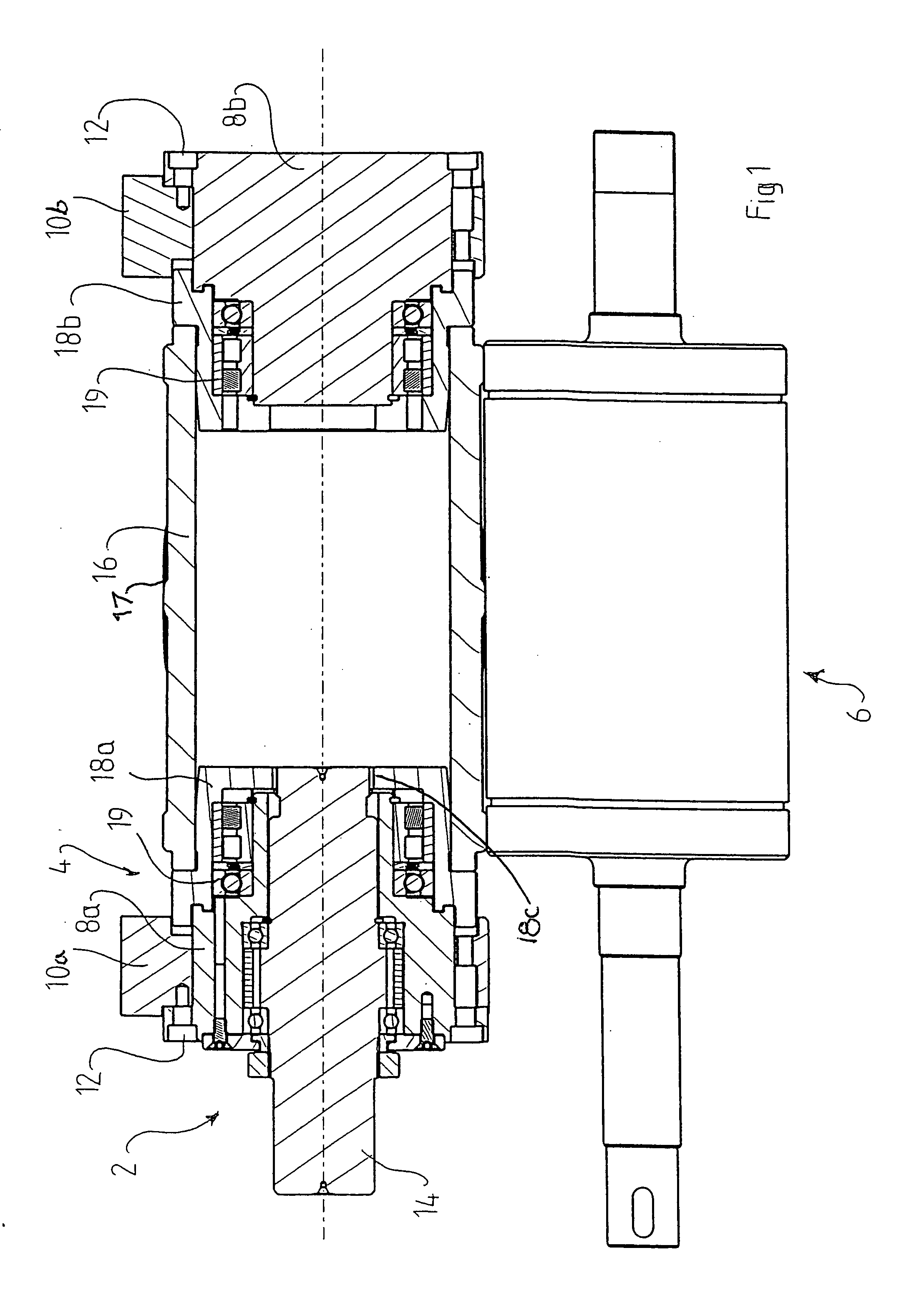
[0021]FIG. 2 shows a rotary cutting apparatus 2′ and a rotary cutter 4′. The static shaft 8′ in this case comprises a single part and is connected to the frame parts 10a′, 10b′ on either side of the mantle 16′ by screws 12′. The rotational movement of the drive axle 14′ is transmitted to the mantle 16′ transmission mechanism which includes gears 20a′, 20b′, 20c′, 20d′. It should be noted that the parts 20b′, 20c′, 20d′ could be produced as two pieces or even one single piece. Centering is performed by means of cylindrical bearings 19′.

[0022] During disassembly, the frame part 10b′ in the right part of FIG. 2 is unsecured from the rest of the frame (i.e. the left frame part remains secured). The mantle 16′ can then be pulled axially away from the tool holder 8′.

third embodiment

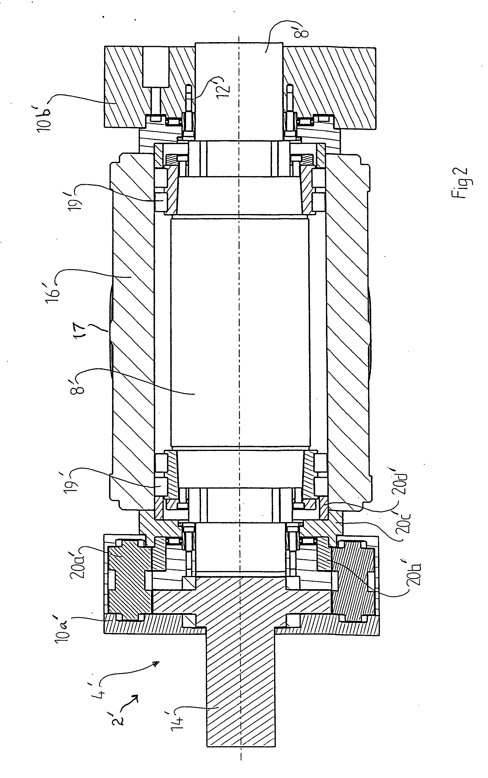
[0023]FIG. 3 shows a rotary cutting apparatus 2″ and a rotary cutter 4″. In this case, the cross-section is such that the cutting member has been omitted. The drive axle 14″ transmits rotational movement directly to the mantle 16″ via a coupling member 22″ which is received in a recess of the mantle. The static shaft 8″ is divided into two shaft members or portions 8a″, 8b″ connected to the respective frame parts 10a″, 10b″ on either side of the mantle 16″. The mantle 16″ is centered relative to the shaft members 8a″, 8b″ and the driving axle 14″ by means of conical bearings 24″.

[0024] For maintenance purposes, the shaft member 8b″ is unsecured from the frame parts 10a″, 10b″, and then the mantle 16″ is released axially from the shaft member 8a″.

[0025] The mantle 16, 16′, 16″ may be made of a multiphase material, such as steel, cemented carbide or cermet (hard phase bonded by a metal).


PUM

PropertyMeasurementUnit
axis of rotationaaaaaaaaaa
pneumatic pressureaaaaaaaaaa
rotational movementaaaaaaaaaa

Abstract

A rotary cutter for a rotary cutting apparatus. The rotary cutter includes a shaft and a mantle having at least one cutting member. The shaft is non-rotatable, and the mantle is rotatably mounted to the shaft and can be removed therefrom in an axial direction. The shaft is adapted to be rigidly mounted in a frame part, wherein the mantle is rotatably arranged relative to the shaft. The shaft may be in the form of a single piece, or a pair of axially spaced shaft portions.

Description

[0001] The present application claims priority under 35 U.S.C. § 119 to patent application Ser. No. 0401734-9 filed in Sweden on Jul. 2, 2004. TECHNICAL BACKGROUND OF THE INVENTION [0002] The present invention relates to a rotary cutter for a rotary cutting apparatus, comprising a shaft and a mantle, the mantle having at least one cutting member. [0003] The invention also relates to a rotary cutting apparatus comprising a frame part, an anvil and such a rotary cutter. [0004] U.S. Pat. No. 4,770,078 discloses in a discussion of the prior art (FIGS. 1-3) a one piece rotary cutter, which has to be removed from the frame when maintenance is needed. In order to allow the machine to be used during maintenance, a further rotary cutter including its static (stationary) shaft must always be accessible. [0005] In order to overcome that problem, U.S. Pat. No. 4,770,078 suggests to divide the rotary cutter into a rotatable shaft and a mantle. The mantle is connected to the rotatable shaft by me...

Claims


Application Information

Patent Timeline
Patent Type & Authority Applications(United States)
IPC IPC(8): B26D7/20B26D1/62B26D7/26B26F1/38
CPCB26D1/626B26F1/384B26D7/265B26D7/2614Y10T83/4795Y10T83/483Y10T83/4838Y10T83/7851Y10T83/9312Y10T83/9377Y10T83/9457Y10T83/9464B26D1/40B26D7/26B26F1/38B26F1/44
Inventor GRENIER, GILBERTMONTEIL, LILLIAN
Owner HYPERION MATERIALS & TECH SWEDEN AB
Why Eureka
Try Eureka