Method of dispensing a fluid with metered delivery

a technology of metered delivery and fluid, which is applied in the direction of rigid containers, volume measurement, packaging goods types, etc., can solve the problems of not being able to dispense fluid on more than one side of the container, being difficult and awkward to use, and devices incapable of substantially equalizing the dose of fluid at each dispensing operation

Active Publication Date: 2008-03-20
1TOUCH HLDG INC
View PDF99 Cites 2 Cited by
  • Summary
  • Abstract
  • Description
  • Claims
  • Application Information

AI Technical Summary

Benefits of technology

[0009] The present invention preserves the advantages of prior art dispensing devices. In addition, it provides new advantages not found in currently available devices and overcomes many disadvantages of such currently available devices.
[0011] The fluid dispensing device includes a container with an interior fluid storage region therein. A flexible metering housing is disposed in fluid communication with the fluid storage region a first one-way valve disposed between the container and the flexible metering housing. One way flow from the interior fluid storage region of the container fills the predetermined volume of the metering chamber with fluid by vacuum action when the flexible metering housing is depressed and then released. A second valve is in fluid communication with the metering housing output port and permits one-way fluid flow from the metering chamber to the exterior outer region of the container when the metering housing is depressed again. Each time the metering housing is depressed a substantially equal volume of fluid is dispensed from the container. An additional foam layer on the outside of container facilitates dispersion and delivery of the fluid.
[0012] It is therefore an object of the present invention to provide a fluid dispensing device that can deliver a substantially equal volume of fluid material from each dispensing operation.
[0016] It is a further object of the present invention to provide a fluid dispensing device that can deliver fluid flow at multiple locations from the device.

Problems solved by technology

However, this yields erratic results where more or less fluid material is delivered on each successive squeeze of the container body.
However, these devices are incapable of delivering a substantially equal dose of fluid at each dispensing operation because they simply open up the container body and permit the fluid to flow to the applicator material by gravity.
Therefore, it is not possible to dispense fluid on more than one side of the container or in a direction opposite to that of gravity.
In view of the foregoing, the fluid dispensing and devices of the prior art suffer from various disadvantages that make them difficult and awkward to use with unexpected results.

Method used


Image

  • Method of dispensing a fluid with metered delivery
  • Method of dispensing a fluid with metered delivery
  • Method of dispensing a fluid with metered delivery

Examples


Embodiment Construction

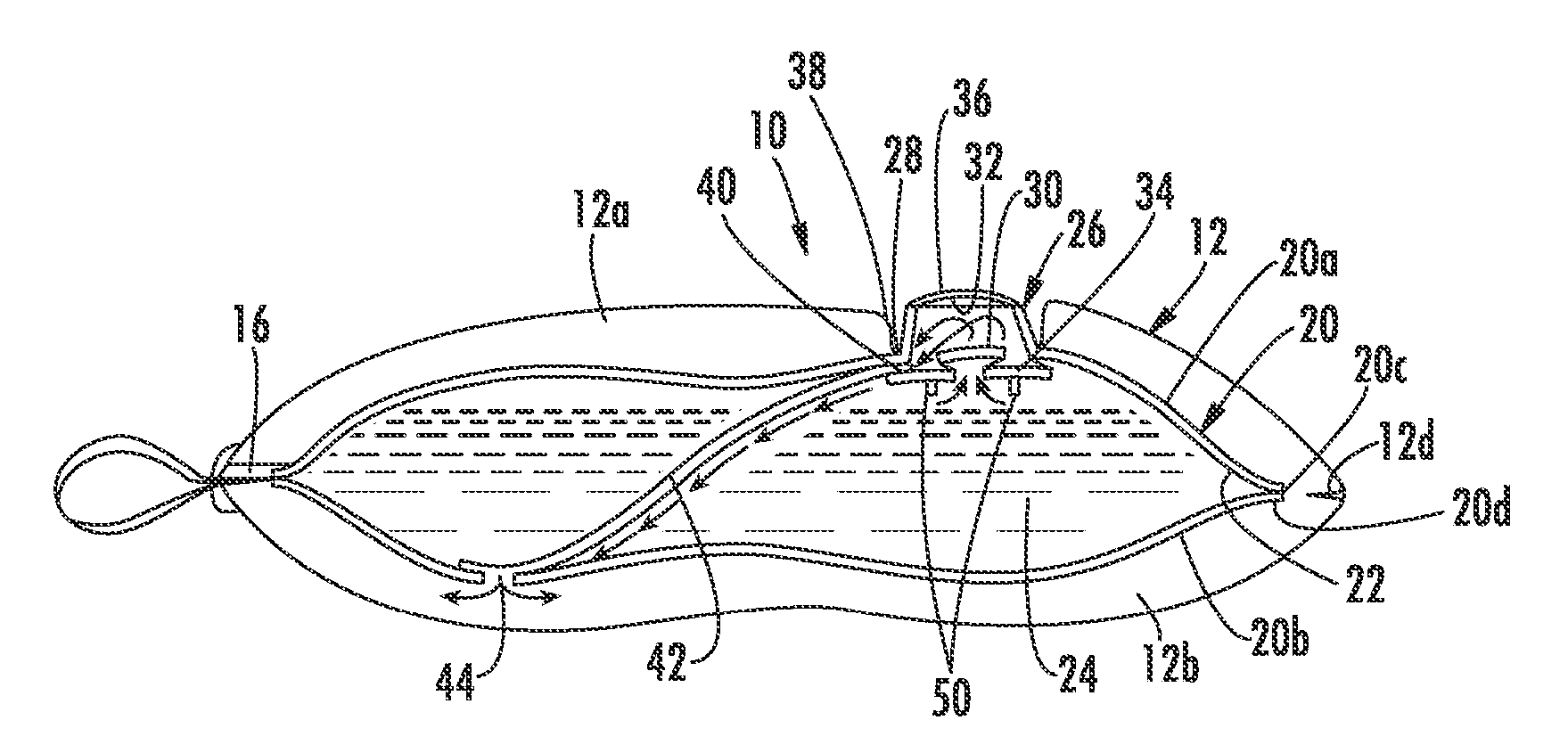
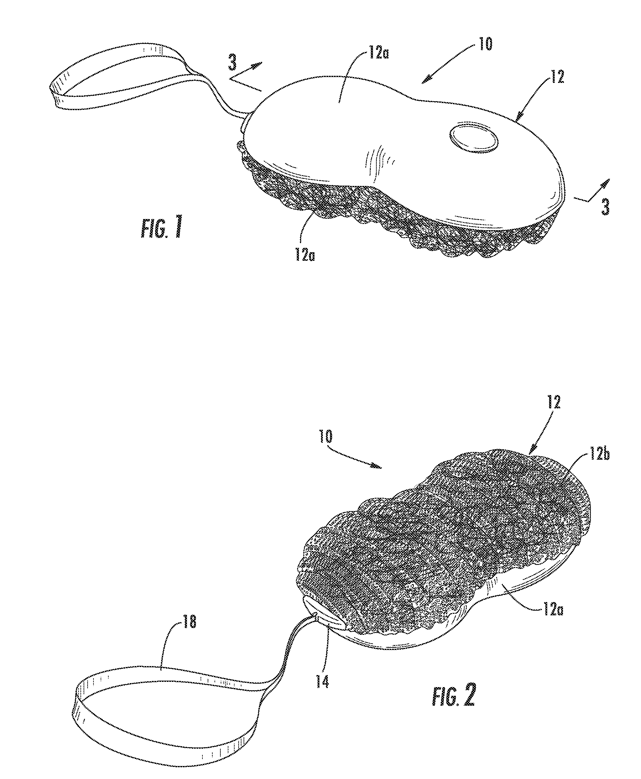
[0027] Referring first to FIGS. 1 and 2, the dispensing device 10 of the present invention is shown to include an outer covering, generally referred to as 12 which serves as an applicator material. This applicator material 12 can be formed of any type of material to suit the application at hand. For example, as seen in FIGS. 1 and 2, the cover 12 is preferably formed of two different types of material 12a, 12a to serve two purposes when in use. Preferably, the top section 12a is of a foam material while the bottom section 12b is of a mesh or “pouf” material. The top section 12a can be secured to the bottom section 12b by, for example, welding. A snap-fit cover 14 seals a re-fill port 16, as will be described in more detail in connection with FIG. 3. A hang strap or cord 18 can also be provided. The configuration of the applicator 12 is just one of many different types of applications of the present invention which will be discussed in more detail below.

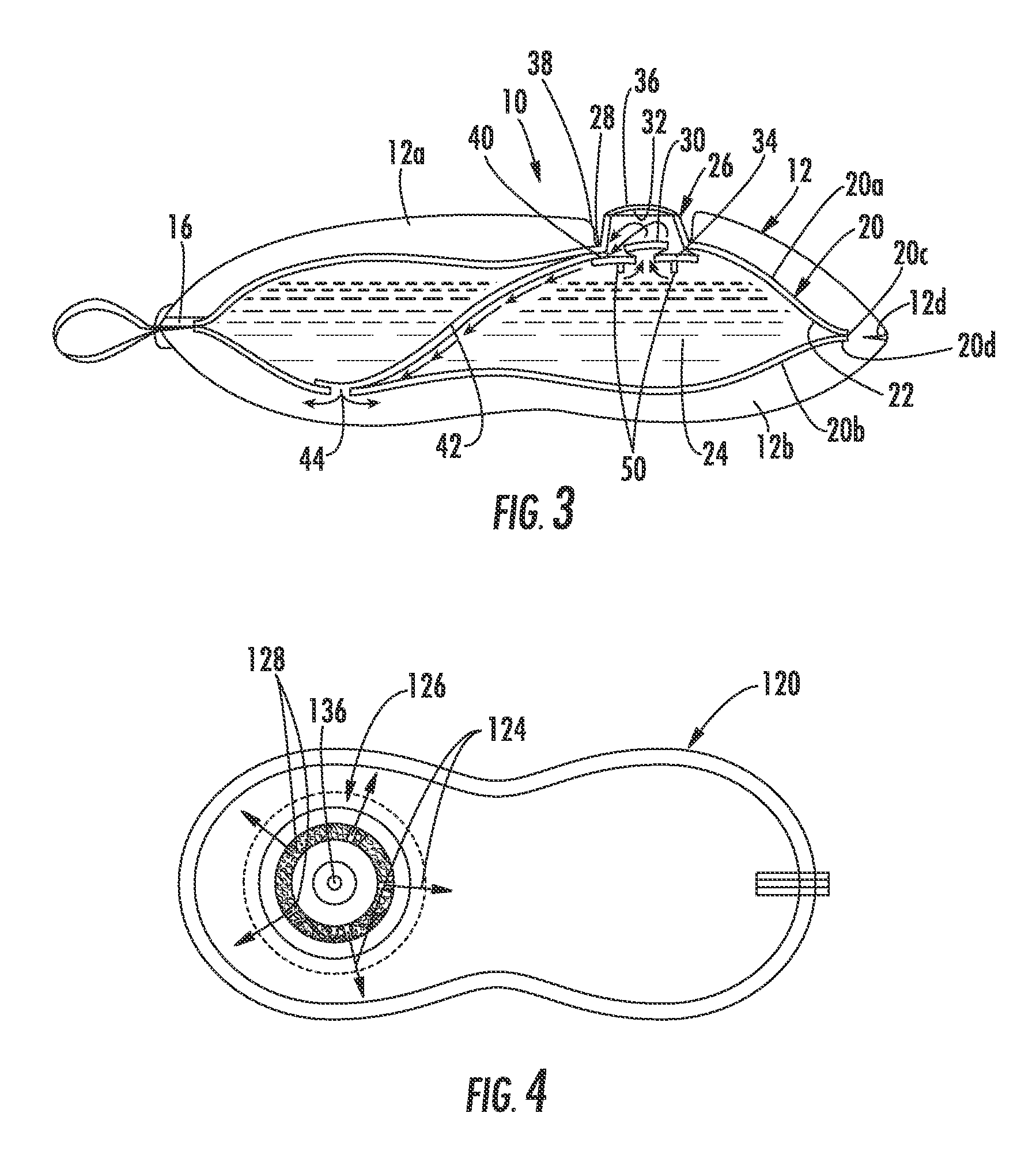
[0028] Turning now to FIG. 3,...


PUM


Abstract

The fluid dispensing device (10) includes a container (20) with an interior fluid storage region (22) therein. A flexible metering housing (26) is disposed in fluid communication with the fluid storage region (22) a first one-way valve (30) disposed between the container (20) and the flexible metering housing (26). One way flow from the interior fluid storage region (22) of the container (20) fills the predetermined volume of the metering chamber (32) with fluid by vacuum action when a button (36) is depressed and then released. A second valve (40) is in fluid communication with the metering housing (26) and permits one-way fluid flow from the metering chamber (32) to the exterior outer region of the container (20) when the metering housing (26) is depressed again. Each time the metering housing (26) is depressed a substantially equal volume of fluid (24) is dispensed from the container (20). An additional foam layer (12) on the outside of container (20) facilitates dispersion and delivery of the fluid (24).

Description

CROSS-REFERENCE TO RELATED APPLICATIONS [0001] This application is a divisonial of U.S. Ser. No. 11 / 074,817, filed on Mar. 8, 2005, which claims priority from prior U.S. Provisional Application Ser. No. 60 / 551,993 filed on Mar. 10, 2004.BACKGROUND OF THE INVENTION [0002] This invention relates generally to dispensing devices and packages. More specifically, the present invention relates to metering devices that can controllably dispense fluid media from a source of fluid media. [0003] Various types of fluid material and media are employed for different purposes through commerce and industry. For example, there are various products in the personal care, home care, air care, transportation care, and food industries that require some type of dispensing of a fluid material from a source of such material. When this material is sold in commerce, it must be contained and stored in some type of container. When that product is used, it must be dispensed from its storage container to a locati...

Claims


Application Information

Patent Timeline
Patent Type & Authority Applications(United States)
IPC IPC(8): B43K5/00G01F11/00B65D37/00A45D34/04A47K5/12A47K7/03B05B11/00B05C17/00B65D35/08B67D7/58
CPCA45D34/04A45D2200/056A45D2200/1018A45D2200/1045A47K5/1208G01F11/025B05B11/3032B05C17/002B05C17/00569B05C17/00583A47K7/03B05B11/1032
Inventor LAFLAMME, ROGERPEKAR, ROBERT
Owner 1TOUCH HLDG INC
Why Eureka
Try Eureka