Sludge source reduction device and sludge source reduction process

A sludge and process technology, applied in the field of sewage treatment, can solve the problems affecting the actual effect of sewage treatment, high cost of sludge treatment and disposal, and entry of pollutants, so as to achieve sludge source reduction, low equipment cost, and prevention of continuous pollution. subsidence effect

Active Publication Date: 2022-07-08
SUN YAT SEN UNIV
View PDF6 Cites 0 Cited by
  • Summary
  • Abstract
  • Description
  • Claims
  • Application Information

AI Technical Summary

Problems solved by technology

[0003] If the sludge produced by the traditional sewage treatment process is not properly treated and disposed of in a timely manner, such as direct export, direct agricultural use, random stacking and irregular landfill, the pollutants in the sludge will enter the soil and surface Water bodies and groundwater systems, causing secondary pollution, which seriously affects the actual effectiveness of sewage treatment
At present, the treatment and disposal of sludge is not optimistic. For example, the main methods of sludge concentration, sludge dehydration and sanitary landfill can only relieve the output pressure of excess sludge to a certain extent. In addition, the above disposal methods themselves There are also limitations
At the same time, the cost of sludge treatment and disposal is high, accounting for about 20% to 45% of the operating costs of sewage treatment plants.

Method used


Image

  • Sludge source reduction device and sludge source reduction process
  • Sludge source reduction device and sludge source reduction process
  • Sludge source reduction device and sludge source reduction process

Examples


Embodiment 1

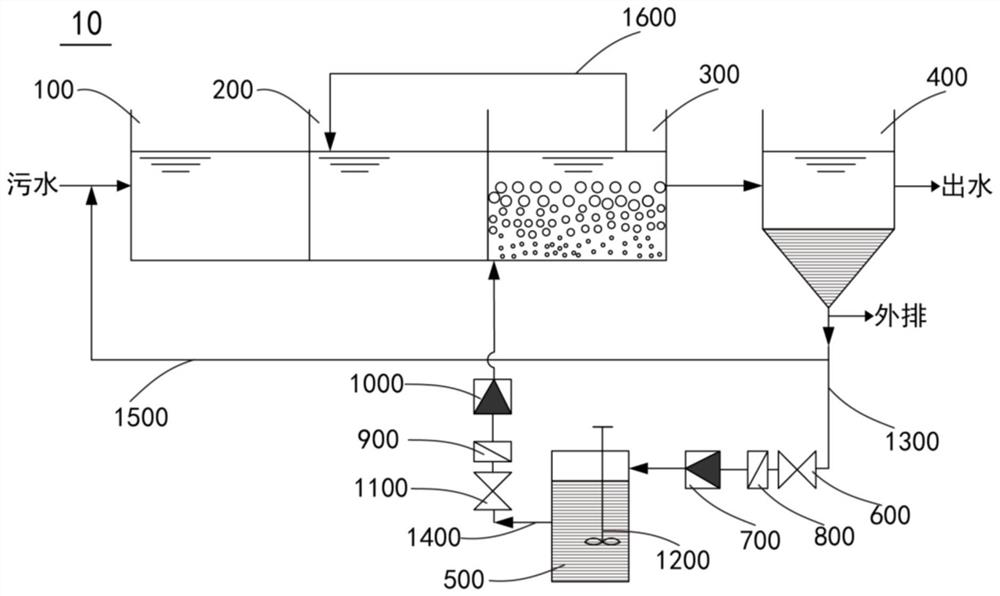
[0088] This embodiment provides a sludge source reduction device 10 .

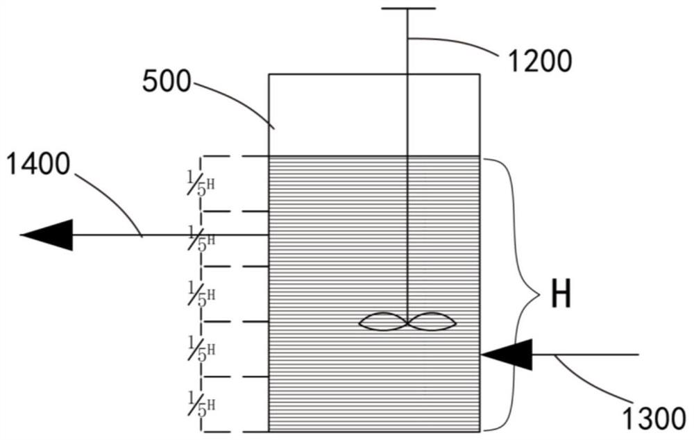
[0089] see figure 1 As shown, a sludge source reduction device 10 includes an anaerobic tank 100, an anoxic tank 200, an aeration tank 300, a secondary sedimentation tank 400, a biological selector 500, a first driving pump 600, and a first flow meter 700. , a first valve assembly 800, a second drive pump 900, a second flow meter 1000, a second valve assembly 1100, a stirring mechanism 1200, a mud inlet pipe 1300, a mud outlet pipe 1400 and a return pipe.

[0090] Along the flow direction of the sewage, the anaerobic tank 100 , the anoxic tank 200 , the aeration tank 300 , the secondary sedimentation tank 400 and the biological selector 500 are connected in sequence. The secondary sedimentation tank 400 is connected to the biological selector 500 through the mud inlet pipeline 1300 . The biological selector 500 is connected to the aeration tank 300 through the mud outlet pipe 1400 . The secondary sedime...

Embodiment 2

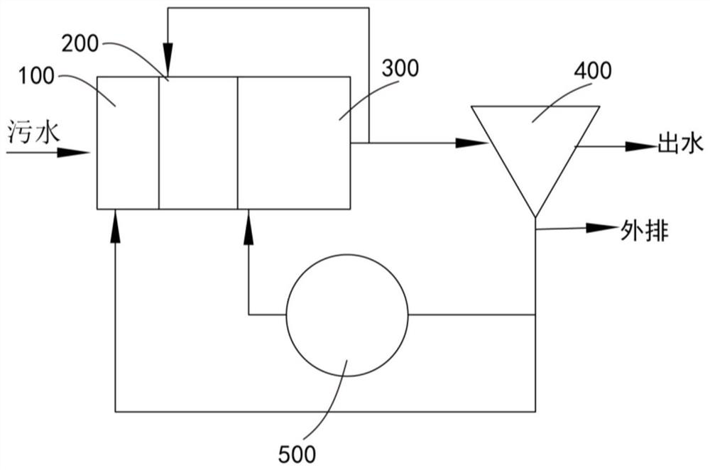
[0096] This embodiment provides a sludge source reduction process.

[0097] see figure 2 As shown, a sludge source reduction process includes the following steps:

[0098] The sewage passes through the anaerobic tank 100, the anoxic tank 200 and the aeration tank 300 for anaerobic treatment, anoxic treatment and aeration treatment respectively.

[0099] The mixed liquid in the aeration tank 300 passes through the secondary sedimentation tank 400 for solid-liquid separation treatment.

[0100] Part of the excess sludge in the secondary sedimentation tank 400 enters the biological selector 500 at a first preset exchange frequency of 4 times / d and stays for a preset time, and the preset time is 10 days. The sedimented sludge in the secondary sedimentation tank 400 enters the biological selector 500 at a sludge return ratio of 10%. Part of the excess sludge in the secondary sedimentation tank 400 is returned to the anaerobic tank 100 .

[0101] The sludge and supernatant gene...

Embodiment 3

[0104] This embodiment uses the sludge source reduction device 10 in Example 1 and the sludge source reduction process in Example 2 to treat sewage.

[0105] In this embodiment, the sewage treatment capacity is 20000m 3 / d, which is 833.33m 3 / h. The hydraulic retention time of sewage in the anaerobic tank 100, the anoxic tank 200, and the aeration tank 300 were 2h, 2h, and 6h, respectively, and the sludge concentration of the aeration tank 300 was 2500 mg / L.

[0106] The quality of the absolute dry sludge discharged from the biological selector 500 every day is as follows: volume of aeration tank 300 = hydraulic retention time x treatment scale = 6h x 833.33m 3 / h=4999.98m 3 ; 300 absolute dry sludge mass in aeration tank M = volume of aeration tank 300 × sludge concentration = 4999.98m 3 ×2500mg / L=12499.95kg; the sludge return ratio is 10%, the absolute dry sludge mass discharged into the biological selector 500 every day is 12499.95kg × 10%=1249.995kg, that is, the abso...


PUM


Abstract

The invention discloses a sludge source reduction device and a sludge source reduction process. The sludge source reduction device of the present invention comprises a biological selector, an anaerobic tank, anoxic tank, aeration tank and a secondary sedimentation tank connected in sequence along the sewage flow direction, and the sludge inlet of the biological selector is connected to the In the secondary sedimentation tank, the mud outlet of the biological selector is communicated with the aeration tank. The sludge source reduction device of the invention can ensure that the sewage treatment meets the standard, and at the same time, realize the reduction of the sludge source, improve the sludge treatment and disposal efficiency, and reduce the sludge treatment and disposal cost.

Description

technical field [0001] The invention relates to sewage treatment technology, in particular to a sludge source reduction device and a sludge source reduction process. Background technique [0002] In recent years, the discharge standards of sewage treatment have become increasingly strict, and the sludge generated in the sewage treatment process is an important bottleneck restricting the healthy development of the sewage treatment industry. [0003] If the sludge generated by the traditional sewage treatment process is not properly disposed of in a timely manner, such as direct outbound transportation, direct agricultural use, arbitrary stacking and non-standard landfills, the pollutants in the sludge will enter the soil and surface. Water bodies and groundwater systems will cause secondary pollution, which will seriously affect the actual effectiveness of sewage treatment. At present, the treatment and disposal of sludge is not optimistic. For example, the main methods of s...

Claims


Application Information

Patent Timeline
Patent Type & Authority Patents(China)
IPC IPC(8): C02F3/30
CPCC02F3/30C02F3/302C02F2303/06C02F2203/004C02F2301/04C02F2209/40Y02W10/20
Inventor 邓欢忠孙连鹏吕慧金辉王昭凯杨裕昊陈传翰
Owner SUN YAT SEN UNIV
Why Eureka
Try Eureka