Sludge treatment method and sludge treatment system

A technology of sludge treatment and treatment method, which is applied in the directions of sludge treatment, water/sludge/sewage treatment, dehydration/drying/thickened sludge treatment, etc. It can solve boiler tail corrosion, sludge conveying system blockage, sewage Solve the problems of limited amount of sludge treatment, achieve the effect of reducing sludge treatment costs, good social and economic benefits, and realizing harmlessness

Active Publication Date: 2011-08-17
JIAXING NEW JIES THERMAL POWER +1
View PDF3 Cites 38 Cited by
  • Summary
  • Abstract
  • Description
  • Claims
  • Application Information

AI Technical Summary

Problems solved by technology

However, in this technology, the wet sludge that has not been dried is directly sent to the furnace for incineration. A large amount of water in the sludge needs to be evaporated in the furnace, resulting in a large amount of flue gas, large pollutant emissions, and serious corrosion at the boiler tail. Evaporation of a large amount of water consumes a lot of energy, the treatment cost is high, and the sludge treatment capacity is also limited to a certain extent. This technology cannot achieve low-cost, large-scale treatment of sludge
In addition, it is reported that the first sludge incineration power generation demonstration project was built using the "coal combustion-supporting circulating fluidized bed" technology in Shaoxing City, Zhejiang Province, China. However, the sludge conveying system of this project is often blocked, resulting in poor operational stability and using Full heat drying process, high energy consumption, low drying efficiency, limited amount of sludge treatment per day, high sludge treatment cost

Method used


Image

  • Sludge treatment method and sludge treatment system
  • Sludge treatment method and sludge treatment system
  • Sludge treatment method and sludge treatment system

Examples


Embodiment Construction

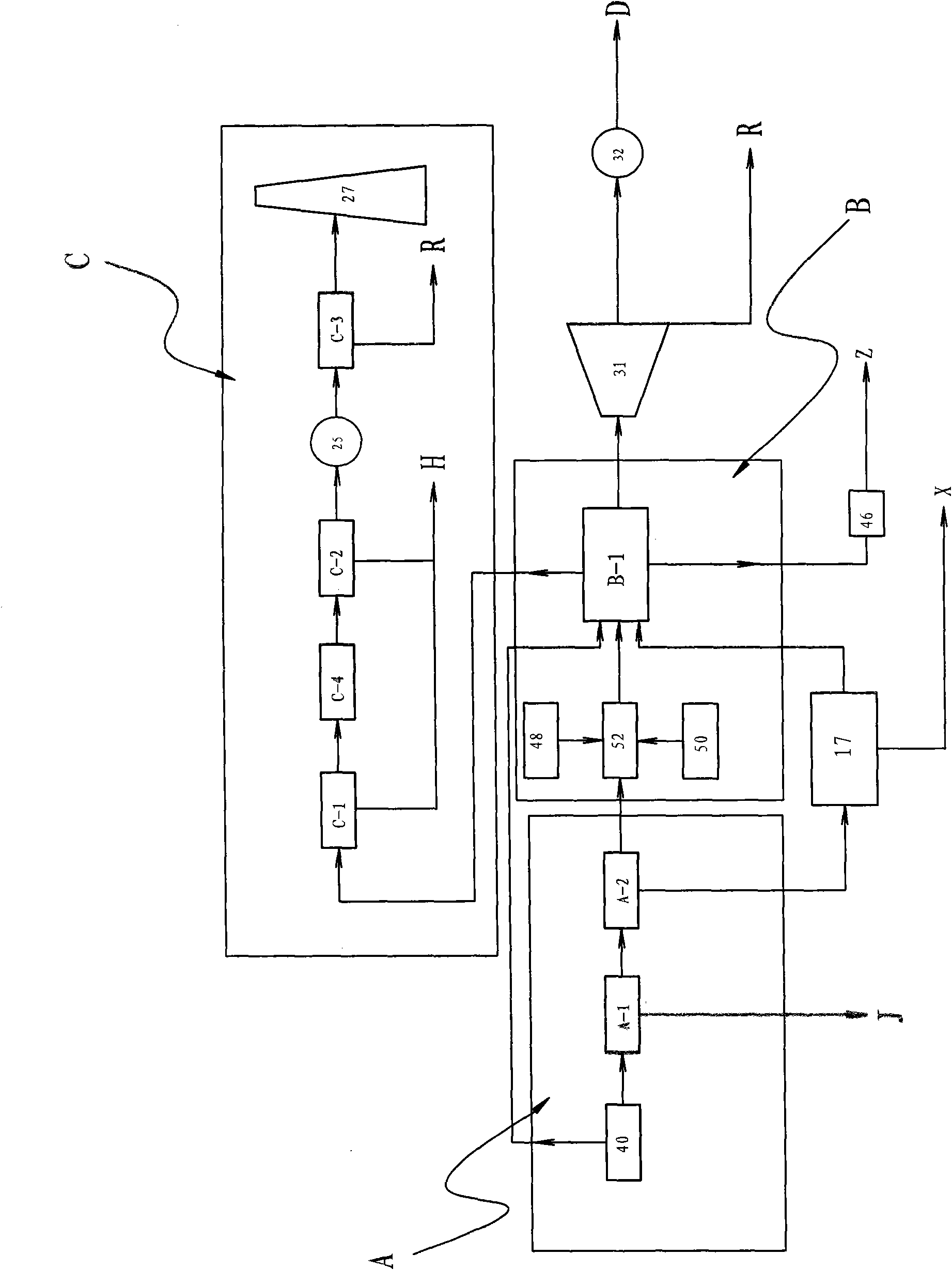
[0034] figure 1 An embodiment of the sludge treatment method according to the present invention is shown, wherein the embodiment includes:

[0035] - drying step A, wherein the wet sludge is dried by a drying device;

[0036] - Incineration step B, wherein the sludge dried in the drying step A is transported to an incinerator and mixed with a combustion aid for mixed incineration;

[0037] - Tail gas treatment step C, wherein the tail gas produced in the incineration step B is discharged after being purified.

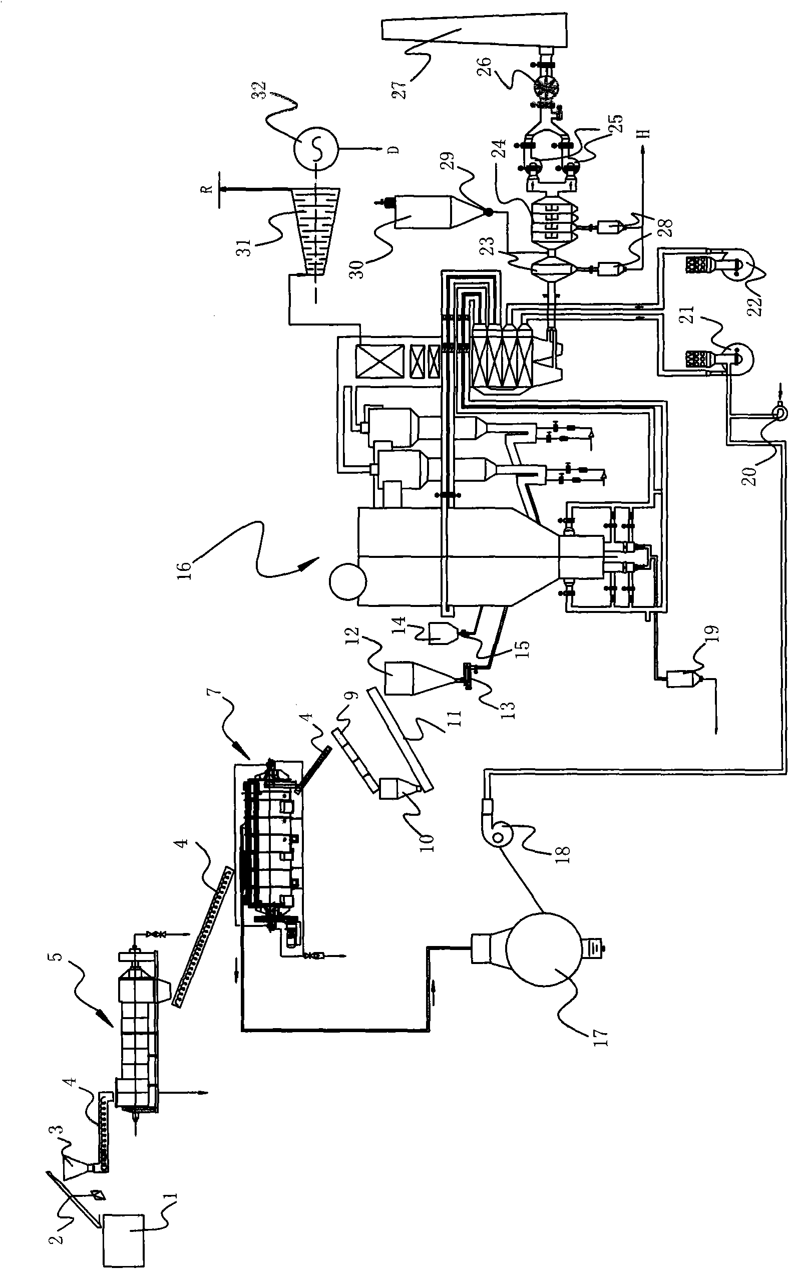
[0038] Combine below figure 1 with 2 To illustrate in detail, at first, in the drying step A, the wet sludge 40 with a water content of 75% to 90% (weight ratio) stored in the wet sludge pool 1 is dried to reduce its water content to A safety threshold, for example around 42%. Wherein, the drying step further includes a deep dehydration step and a thermal drying step. in:

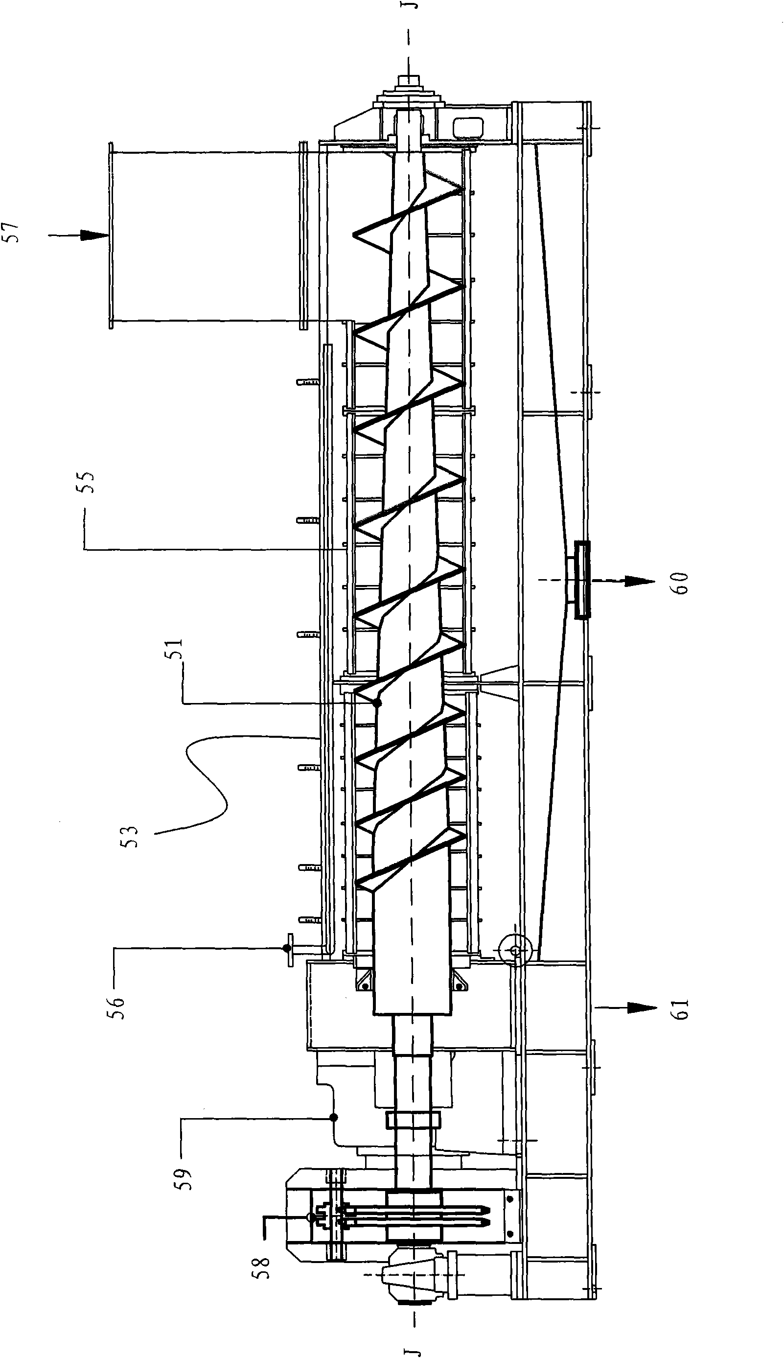
[0039] - First carry out the deep dehydration step A-1. In this step, first put the wet sl...


PUM


Abstract

The invention provides a sludge treatment method which comprises the following steps: drying: drying sludge through a drying device; combusting: feeding the sludge dried in the drying step to a combustion furnace, mixing a combustion improver with the dried sludge, and carrying out mixed combustion; and tail gas treatment: treating the tail gas generated in the combustion step, and discharging. The sludge treatment system comprises the combustion furnace and a tail gas treatment device, wherein the combustion furnace is used for burning the sludge; and the tail gas treatment device is used for treating the tail gas generated after the sludge is burned by the combustion furnace. The sludge treatment system is characterized by further comprising a sludge drying device and a sludge conveyer, wherein the sludge drying device is arranged in front of the combustion furnace and is used for drying the sludge to be burned by the combustion furnace; and the sludge conveyer is convenient for delivery of the sludge in the sludge drying device. The method and system provided by the invention have the advantages that the cost is low, and effect is good.

Description

technical field [0001] The invention relates to the disposal of wet sludge, in particular to a composite sludge treatment method and a sludge treatment system. Background technique [0002] As a regular product of urban sewage treatment plants and industrial enterprise sewage treatment stations, sludge plays an important role in the process of energy saving, emission reduction and ecological construction. Sewage treatment plants in cities and enterprises in our country produce a large amount of wet sludge every day, and sludge is the concentration of pollutants in the water treatment process, mainly composed of microbial cell groups and their disintegration products. In addition to high organic matter content, it also contains a large amount of Harmful substances such as heavy metal ions and pathogenic bacteria, and have the characteristics of high water content, large volume, complex shape, and difficult transportation. If the sludge is not treated in a timely and effectiv...

Claims


Application Information

Patent Timeline
Patent Type & Authority Applications(China)
IPC IPC(8): C02F11/00C02F11/12F23G7/00B01D53/78B01D53/50B01D50/00
CPCY02W10/37
Inventor 俞保云孟志浩章平衡庄建发计荣林胡宁余晓华吴斌
Owner JIAXING NEW JIES THERMAL POWER
Why Eureka
Try Eureka