Control System for Influencing Test-environment Parameters, Method for Controlling a Microscope System and Computer Control Program for Same

Active Publication Date: 2008-03-20
CARL ZEISS MICROSCOPY GMBH
23 Cites 7 Cited by

AI-Extracted Technical Summary

Problems solved by technology

One disadvantage associated with such conventional control instruments lie in the fact that a human user has to become active to change a test-environment parameter and also, possibly, to log the current value of the test-environment parameter, which may be important for a later evaluation of the data material acquired with the microscope system.
An extensive auto...

Benefits of technology

[0008] A control module according to one embodiment of the invention for influencing a test-environment parameter of an incubation system comprises an interface unit, which in use is to be coupled with a bus, for receiving a control command, a control device, which is coupled with the interface unit and is configured to influence the test-environment parameter in a manner depending on the control command, and a further interface unit which is coupled with the interface unit and via which the received control command is o...

Abstract

A microscope configuration according to an exemplary embodiment includes a microscope system with at least one addressable component and also a control system with a plurality of control modules for influencing a plurality of test-environment parameters in a test chamber of the microscope system. The control modules are configured to be combined in modular manner and to be coupled through an interface unit with a unified bus, through which they are controlled. A control module influencing a test-environment parameter of an incubation system has a control command interface unit configured to receive at least one control command. The control command interface unit couples with a bus. A control device is coupled with the control command interface unit and influences the test-environment parameter based upon the control command. A further interface unit is coupled to the control command interface unit and outputs, again, the received control command.

Application Domain

Temperature control without auxillary powerTemperature control with auxillary non-electric power +8

Technology Topic

Test roomMicroscope +6

Image

  • Control System for Influencing Test-environment Parameters, Method for Controlling a Microscope System and Computer Control Program for Same
  • Control System for Influencing Test-environment Parameters, Method for Controlling a Microscope System and Computer Control Program for Same
  • Control System for Influencing Test-environment Parameters, Method for Controlling a Microscope System and Computer Control Program for Same

Examples

  • Experimental program(1)

Example

[0032] Aspects of the invention are disclosed in the following description and related drawings directed to specific embodiments of the invention. Alternate embodiments may be devised without departing from the spirit or the scope of the invention. Additionally, well-known elements of exemplary embodiments of the invention will not be described in detail or will be omitted so as not to obscure the relevant details of the invention.
[0033] Before the present invention is disclosed and described, it is to be understood that the terminology used herein is for the purpose of describing particular embodiments only and is not intended to be limiting. It must be noted that, as used in the specification and the appended claims, the singular forms “a,”“an,” and “the” include plural references unless the context clearly dictates otherwise.
[0034] While the specification concludes with claim defining the features of the invention that are regarded as novel, it is believed that the invention will be better understood from a consideration of the following description in conjunction with the drawing figures.
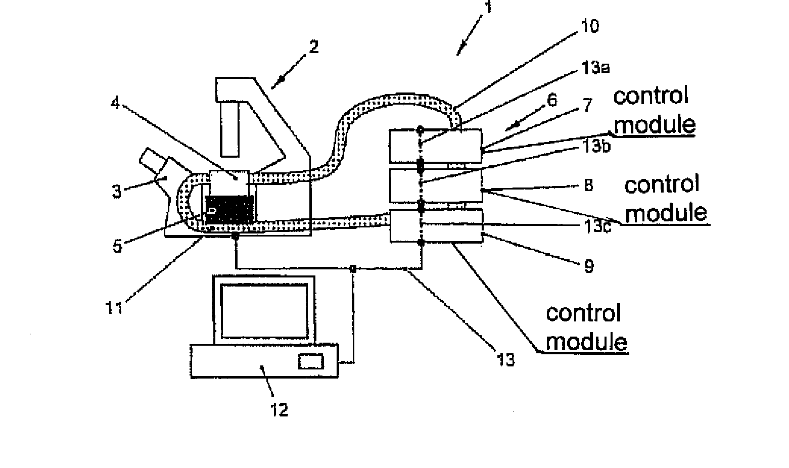
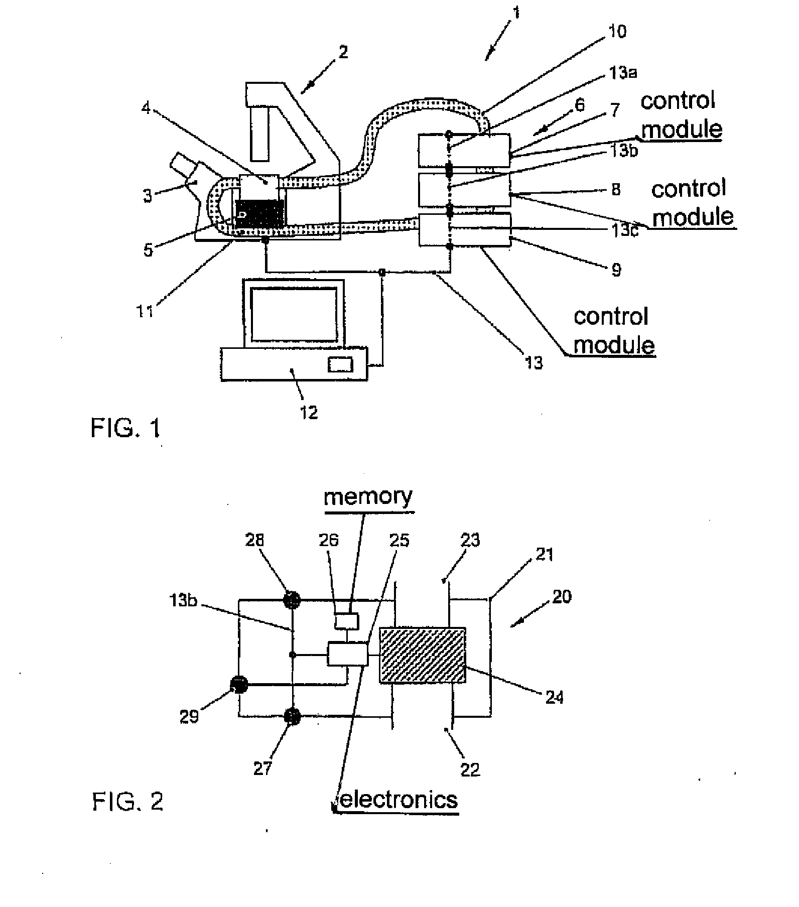
[0035]FIG. 1 shows a microscope arrangement 1 according to one embodiment of the invention which comprises a microscope system 2 and a control system 6 for influencing a plurality of test-environment parameters for a specimen to be observed with the microscope system 2. The microscope system 2 includes a microscope 3 which may have all the standard components of a microscope and which is used for observing a specimen in a test chamber 4. The microscope system 2 further includes at least one addressable component 5. The addressable component 5 may, for example, include a microscope stage, capable of being displaced by a motor, for positioning the specimen in three directions in space, a device for specimen manipulation, such as perfusion for example, optical or mechanical forceps, a device for supplying active substances etc., or an illumination device for illuminating the specimen to be observed, whereby, for example, the spectrum or the intensity of the illumination device can be controlled and changed. The addressable component 5 may also be or include a device for image-recording, such as, for example, a camera which can be tripped by an electrical signal. If a plurality of addressable components are provided on the microscope system, these may be controlled simultaneously or sequentially.
[0036] The control system 6 serves for controlling a plurality of parameters in the test chamber 4. The control system 6, which includes a plurality of control modules 7-9 which will be explained in detail below, is connected to the test chamber 4 via a pair of air lines 10, 11, and, together with the test chamber 4 and the air lines 10, 11, forms an incubation system. Each control module 7-9 of the control system 6 controls a parameter of the test environment in the test chamber 4. Possible test-environment parameters include, for example, an oxygen content, a carbon-dioxide content, an air humidity and an air temperature of the air in the test chamber 4, or a temperature of a test stage or of a specimen-holder configuration, of a heating element for the objective or of test chambers. The test-environment parameters that relate to the atmosphere surrounding the specimen are controlled by the control system 6 by guiding air into the test chamber 4 by the control system 6 via the air line 10 and flowing around the specimen there. At the same time, air is aspirated out of the test chamber 4 by the control system 6 via the air line 11 and is reprocessed. As indicated in FIG. 1, the air is conveyed between control module 9 and control module 8 and also between control module 8 and control module 7, in each instance via corresponding air-line connecting pieces. In each of the control modules 7-9, a parameter of the air to be conducted into the test chamber 4 is respectively adjusted, to realize desired, defined conditions in the test chamber 4. The control modules are preferably arranged in such a manner in the direction of flow of the air flowing in the test chamber 4 that a variable that is set by one of the control modules is not influenced, or is barely influenced, by the following control modules. For instance, control module 9 may be a control module for controlling the carbon-dioxide content, control module 8 may be a control module for controlling the oxygen content, and control module 7 may be a control module for controlling the air temperature. Each control variable is set in the control system 6 by only one control module 7-9—i.e. the control variables of the control modules 7-9 are different from one another in pairs, and there is no redundancy.
[0037] Both the addressable component 5 of the microscope system 2 and the control modules 7-9 of the control system 6 are driven by an electronic computer system 12, for example in the form of a conventional computer or a separate electronic operating unit. For this purpose, the addressable component 5 of the microscope system 2, the control system 6 and the computer 12 are connected to a common bus system 13, by virtue of which it becomes possible for the communication between the various components involved to be handled via a unified bus system and a unified bus protocol. The bus protocol may be any suitable bus protocol, for example a CAN protocol, an RS232 protocol or a USB protocol. Both the microscope system 2 and the control system 6 have corresponding interfaces. As already mentioned above, in this connection the term ‘unified bus protocol’ denotes a bus protocol under which the control modules are driven in unified manner at the application layer.
[0038] As represented schematically in FIG. 1, portions 13a-13c of the bus 13 take the form of integrated constituents of the control modules 7-9—i.e. the control modules 7-9 are respectively configured to output a signal received at an interface again, to another of the control modules, via a further interface. In this way, in particular a serial bus architecture, but also a parallel bus architecture, may be formed. As will be explained in greater detail in the following, the control modules 7-9 may be configured in such a manner that the electrical coupling which is necessary between the interfaces of various control modules is established automatically if the control modules 7-9 are stacked one on top of the other, as shown in FIG. 1. Similarly, the air connections between the control modules are also established automatically if the latter are stacked on top of one another.
[0039] With reference to FIG. 2, a control module according to an exemplary embodiment of the invention will next be explained in greater detail. The control module 20, which is only represented schematically in FIG. 2, may, for example, be used by way of control module 7 or 8 of the control system 6 shown in FIG. 1.
[0040] The control module 20 includes a housing 21 in which an air inlet 22 is formed on a lower side face, and an air outlet 23 is formed on an upper side face. The air inlet 22 and the air outlet 23 serve respectively for receiving and for outputting the air that is to be conducted into the test chamber of the microscope system 4. The air inlet 22 and the air outlet 23 are connected to a conduit in the control module 20, so that the air is guided through the control module from the air inlet 22 to the air outlet 23. At the conduit for the air, a device 24 for influencing a parameter of the air is provided. The configuration and mode of operation of the device 24 depends on the variable to be influenced by the control module 20 or may, for example, include a heating element or several heating elements if the control module serves for controlling the air temperature, or may include a valve if the control module serves for controlling the oxygen content or the carbon-dioxide content of the air. In the latter case, containers, which are typically provided outside the control module 20, for the corresponding gas—nitrogen for displacing oxygen, or carbon dioxide—are provided, from which nitrogen or carbon dioxide can be fed into the stream of air flowing through the control module 20. The device 24 is coupled with control-module electronics 25 which, in turn, are connected to a control-module memory 26. Saved in the memory 26 is a set value for the test-environment parameter to be controlled by the control module 20, which is read out by the control-module electronics 25 which, in turn, drive the device 24 in a manner depending on the set value. The set value is communicated to the control module 20 in the form of a corresponding control command via the bus 13. The control-module electronics 25 are connected to the interface 27 which is to be coupled with the bus 13 in order to evaluate the control command received via this interface 27. For a bus architecture as represented in FIG. 1, the control command includes address information that identifies the control module to which the control command is directed and that is to be actuated on the basis of the control command. The control-module electronics 25 are configured to read out the address information from the control command and in this way to ascertain whether the control command is intended for the control module 20. In this case only, the control command is subjected to further processing, the set value for the test-environment parameter transmitted with the control command is ascertained, and is saved in the control-module memory 26.
[0041] As already mentioned above with reference to FIG. 1, the bus 13 is connected through the control module 20. For this purpose, the control module 20 includes a further interface unit 28 which is coupled with the interface unit 27 and via which a signal received via the interface unit 27 is transmitted to the next control module.
[0042] The control module 20 has a further port 29 which is coupled with the control-module electronics 25 and serves to receive a signal from a sensor provided in the test chamber 4 of the microscope system 2. This signal—which, for example, may be a simple voltage signal—corresponds to the actual value of the test-environment parameter to be controlled by the control module 20. This actual value is likewise stored in the control-module memory 26. In response to a corresponding enquiry addressed to the control module 20, which is received in the form of a command via the interface 27, the control-module electronics 25 read out the actual value from the control-module memory 26 and communicate said value to the computer 12 via the interface 27 and the bus system 13. In this way, it becomes possible to log the actual values in the test chamber automatically by means of the computer 12. The sensor port 29, however, does not necessarily have to be provided in the control module 20. In particular, it is also possible to connect sensors in the test chamber 4 to the computer 12 in some other way, for example via an interface of the microscope system. As will be explained in further detail below, sensors may also be integrated within the control modules.
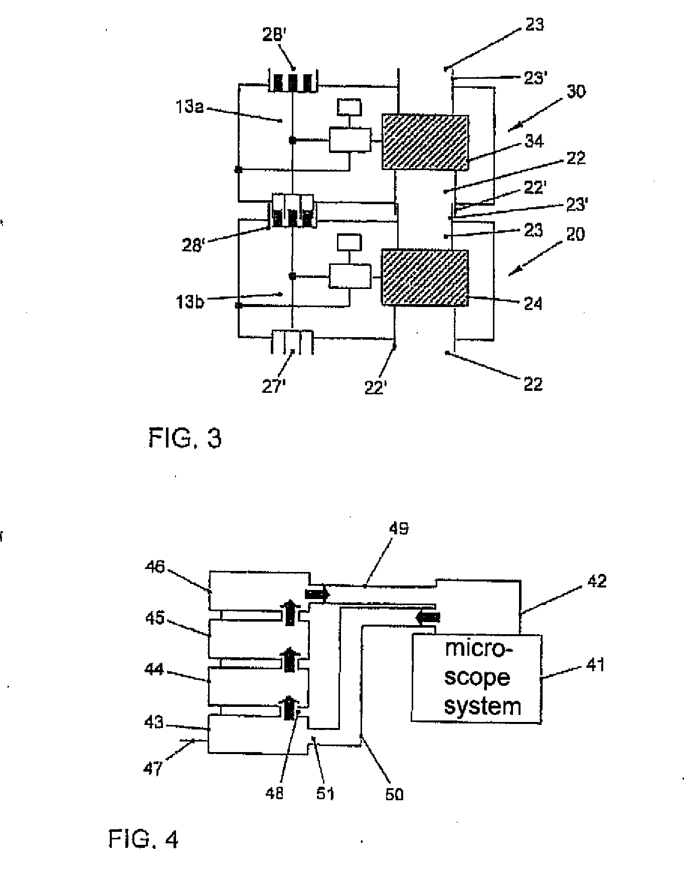
[0043] With reference to FIG. 3, the combination of various control modules 20, 30 so as to form a control system will next be explained. The structure of control module 30 is substantially identical to the structure of control module 20 explained with reference to FIG. 2, but exhibits a different device 34 by which the air flowing through control module 30 is influenced, since control module 30 controls a test-environment parameter different from that controlled by control module 20.
[0044] In order to combine several control modules 20, 30 so as to form a control system, electrical connections may need to be established between the interface unit or the further interface unit of the control modules 20, 30 and the air inlet or air outlet of these control modules 20, 30. Whereas connections of such a type may also be realized by means of suitable cables or air lines, the control module shown in FIG. 2 is configured in such a manner that the corresponding connections are established automatically if the control modules 20, 30 are stacked on top of one another, as will be explained in the following. For the purpose of better illustration, the interface units 27′ or the further interface units 28′ of the control modules 20, 30 have been exemplarily represented not only schematically but in the form of plug-in connections. The interface unit 27′ and the further interface unit 28′ of each of the control modules 20, 30 are in this case configured as complementary connectors, so that the further interface unit 28′ of one of the control modules is capable of being coupled directly with the interface unit 27′ of another control module. For instance, the interface unit 27′ may be configured as a male RS232 connector, and the interface unit 28′ may be configured as a female RS232 connector. Similarly, the air inlet 22 and the air outlet 23 of each control module 20, 30 also have a complementary configuration. In FIG. 3 the connecting portions 22′ and 23′ of the air inlet 22 and of the air outlet 23, respectively, protruding from the respective housing of the control module 20, 30 are configured in such a manner that the connecting portion 22′ of the air inlet 22 is capable of being connected to a connecting portion 23′ of the air outlet 23 of a control module with identical configuration of the air inlet and air outlet. In the example represented in FIG. 3 the connecting portion 23′ of the air outlet 23 of the control module 20 can be introduced in sealing manner into the connecting portion 22′ of the air inlet 22 of the control module 30. By virtue of this structural design of the control modules 20, 30 an air connection is established automatically between the air conduits of the control modules, and an electrical connection is established automatically between the portions of the bus 13 extending within the control modules. The positioning of the control modules 20, 30 relative to one another may in this case be assisted by guide devices (not shown) such as, for example, pins or recesses in the upper or lower side faces of the control modules 20, 30.
[0045] In a control system that includes a plurality of control modules, each control module does not have [[has]] to be configured as described above. In particular, in the case of [[a]] stacking [[of]] control modules one on top of the other it is desirable [[that]] for the air inlet 22 and the interface 27 of the lowest control module of the control system [[are]] to be provided, not on the lower side face, but on a more readily accessible lateral side face. As represented schematically in FIG. 1, this can be realized, for example, by providing the air inlet 22 and the interface unit 27 on a lateral side face of the housing of the control module.
[0046] Whereas in the exemplary embodiment shown in FIGS. 1-3 the control modules have been configured in such a way that they are stackable, the corresponding electrical connections and air connections being established automatically by virtue of the stacking, in another exemplary embodiment the control modules may also be configured in such a way that the air inlet 22 and the interface unit 27 are provided on a lateral side face, for example on the left side face, of the housing, and the air outlet 23 and the further interface unit 28 are provided on the other lateral side face, for example on the right side face. In this case the corresponding electrical connections and air connections may be established automatically if the control modules are arranged laterally side by side.
[0047] Although not shown in FIGS. 2 and 3, it will be understood that the control module 20 may include further components, such as, for example, an internal sensor for ascertaining one or more parameters of the air, which is coupled with the control-module electronics 25, the actuation of the device 24 being effected in a manner depending on a value ascertained by the internal sensor. For instance, the sensor may ascertain the temperature of the air flowing in at the air inlet 22, and a heating power of the device 24 may be set in a manner depending on this input temperature, in order to achieve a desired output temperature for the air.
[0048] With reference to FIG. 4 and FIGS. 5A and 5B, various ways of guiding air between the control modules of the control system and the test chamber of the microscope system will next be described. Identical or similar elements have been provided with the same reference symbols in FIGS. 4, 5A and 5B. Represented schematically is a microscope system 41 with a test chamber 42, and also a control system with a plurality of control modules 43-46. As already described above, the control modules are controlled, e.g., by a computer or an operating unit via a bus 47. Air is guided between the control modules 43-46 via air-connection portions 48 which are only indicated schematically, the airflow direction being indicated schematically by arrows. In the exemplary embodiment represented in FIG. 4, in which the flow of the air is substantially identical to the exemplary embodiment shown in FIG. 1, the air to be conducted into the test environment is conducted into the test chamber 42 through control module 46 via an air connection 49. At the same time, air from the test chamber 42 is aspirated via an air line 50 into control module 43 which has a suction opening 51 for the air from the test chamber 42. The aspirated air then passes through the air conduits in the control modules 43-46, where the various parameters of the air, such as, for example, its temperature, its humidity, its oxygen content or its carbon-dioxide content, is influenced in accordance with the corresponding function of the control modules. The air is subsequently supplied to the test chamber 42 again via the air line 49. FIG. 4 is consequently an example of a circulating airflow.
[0049] In the exemplary embodiment shown in FIG. 5A the suction opening 51 of control module 43 is not connected to the test chamber via an air line. Rather, control module 43 aspirates fresh air at the suction opening 51, said air subsequently being guided through the control modules 43-46, whereby, in turn, the parameters of the air are influenced or controlled in each instance in a manner corresponding to the control functions of the individual control modules. After passing through all the control modules, the air is guided from control module 46 to a test chamber 52 via the air line 49. In the exemplary embodiment shown in FIG. 5A the test chamber 52 has no opening through which the air would be supplied from the test chamber 52 to the control modules again. Rather, the test chamber 52 includes an outlet opening 54 through which air from the test chamber 52 is blown out into the environment. Although the exit opening 54 in FIG. 5A has been represented as an opening in the wall of the test chamber 52, it may also be configured in another way, for example by a cover which upwardly seals the test chamber 52 resting only loosely on the side walls of the test chamber, so that in the case of an excess pressure in the test chamber 52 the cover is lifted minimally and air is consequently able to escape passively.
[0050]FIG. 5B shows a further exemplary embodiment which is a modification of the exemplary embodiment shown in FIG. 5A and in which a stream of air is conducted in circulating manner through all the control modules 43-46. For this purpose, the outflow opening of control module 46 is connected to the suction opening 51 of control module 43 via an air line 55. A small partial stream of air, which has been represented schematically by smaller arrows, is branched off in control module 45 from the circulating stream of air and guided to the test chamber 52 via the air line 56. Fresh air or gases can be aspirated via suction openings (not represented) in the control modules, in order to keep the total quantity of the air circulating through the control modules approximately constant.
[0051] It should be observed that, whereas in the exemplary embodiments shown in FIGS. 1, 4, 5A and 5B the air to be conducted into the test chamber is guided through all the control modules, in other embodiments the air may be guided through only some or only one of the control modules of the control system. For instance, one of the control modules may have been set up in order to control a specimen-holder temperature in the test chamber. To do this, it is not necessary to cause the air that is to be conducted into the test chamber to flow through this control module.
[0052] As has already been explained above, the control system—and, in particular, also each individual control module—may be configured to be controlled together with the addressable component of the microscope system via a unified bus system. The controlling of the various components, in particular of the addressable component 5 of the microscope system 2 and also of the control modules 7-9 of the control system 6, may be effected in this case by means of the computer 12, which has been programmed to drive these components automatically. A sequence of instructions to be processed by the computer, which are stored on a storage medium in the form of a computer-program product, may then offer a unified operator interface which enables both the control of the control system and of the addressable component of the microscope system and a documentation of various experimental parameters and the control of an image-recording by the microscope system to be performed. By virtue of the fact that both the various control modules of the control system for influencing test-environment parameters and one or possibly even more addressable components of a microscope system may be controlled by the computer 12 under a unified operator interface, it becomes possible to match complex sequences optimally to one another during the course of an experiment.
[0053] With reference to FIG. 6, a method 60 according to an exemplary embodiment of the invention will next be described which is executed by the computer 12 in order to control the control system, which influences the test-environment parameters, and an addressable component of the microscope system. In the case of the exemplary method that is represented in FIG. 6, the addressable component of the microscope system is a recording device, such as a camera for example. Firstly, in step 61 the temporal recording-intervals in which the camera has to make recordings of the specimen material in the test chamber are entered into the computer 12 by a user. Furthermore, the user defines an experimental schedule—i.e. for example, a fixed set of test-environment parameters or typically the temporal change in various test-environment parameters during the experiment. The experimental schedule can be input in any suitable manner that is expedient and convenient for the user, for example by the user specifying that a particular test-environment parameter is to increase in linear manner from a first value to a second value within a predetermined time-interval, or that the test-environment parameter is to assume a new value abruptly at particular times. On the basis of the experimental schedule input by the user and on the basis of the recording-interval, in step 62 the computer generates a time-phased schedule which contains the times sti at which a control command for one of the control modules is to be generated in order to bring about a change in the corresponding test-environment parameter, and also the times mtj at which the camera of the microscope system has to be driven in order to record an image. The following steps 63-67 are repeated until the experiment is terminated by a renewed user input or until a predetermined maximum experiment-time has been reached. Firstly, in step 63 a time t elapsed since the start of the experiment is registered, for example on the basis of the system time of the computer 12. Subsequently, in step 64 it is ascertained whether the current time t is equal to one of the previously ascertained times sti at which one of the control modules is to be controlled. If this is the case, in step 65 a corresponding module control command is generated and output to the bus 13. As has already been explained earlier, the module control command may contain, in particular, address information relating to the identification of the control module that is to be controlled by the command. Subsequently, in step 66, it is ascertained whether the current time t is equal to one of the times mtj at which the addressable component—i.e. in this case, the camera—of the microscope system has to be controlled or actuated. If this is the case, in step 67 a microscope control command is next generated. As has likewise already been discussed above, the microscope control command may also contain address information, on the basis of which the addressable component of the microscope system is identified. Subsequently steps 63-67 are repeated.
[0054] It is evident that the exemplary method 60 shown in FIG. 6 includes only fundamental control functions for the control system for influencing test-environment parameters and the addressable component of the microscope system. Further functions may, however, be easily integrated into the method. Functions of such a type may, for example, include an automatic storage of recorded images, possibly supplemented by the simultaneous storage of additional information, such as the current time at the time of the recording, or current test-environment parameters, or the logging and/or evaluation of test-environment-parameter values.
[0055] Whereas, in the exemplary embodiments previously discussed in detail where the microscope system respectively has only one addressable component, a plurality of addressable components of the microscope system may also be controlled together with the control system via a unified bus system. Similarly, as discussed in the preceding exemplary embodiments, the bus system does not have to include a plurality of control modules, but may also be a single control module. In this case the individual control module and the addressable component of the microscope system can also be controlled using the method described with reference to FIG. 6.
[0056] Whereas exemplary embodiments of the present invention have been described above with reference to a microscope arrangement, the control modules and the control system for influencing test-environment parameters may find application not only in microscope arrangements but generally in any incubation system.
[0057] Summing up, according to exemplary embodiments of the present invention a control module for influencing a test-environment parameter of an incubation system, a control system for influencing a plurality of test-environment parameters, a method of controlling a microscope arrangement with a control system and a computer-program product are provided which enable a simplified data communication between the various components involved, using a unified bus system, and consequently provide a user-friendly, unified control of the various components under an operator interface by means of a computer system.

PUM

no PUM

Description & Claims & Application Information

We can also present the details of the Description, Claims and Application information to help users get a comprehensive understanding of the technical details of the patent, such as background art, summary of invention, brief description of drawings, description of embodiments, and other original content. On the other hand, users can also determine the specific scope of protection of the technology through the list of claims; as well as understand the changes in the life cycle of the technology with the presentation of the patent timeline. Login to view more.
Why Eureka
Try Eureka