
Uniform aerosol deposit sampling device

a sampling device and aerosol technology, applied in auxillary pretreatment, instruments, separation processes, etc., can solve the problems of air stream pressure differences, turbulent air flow, and air flowing turbulent or vortices, and achieve the effect of uniform distribution

Inactive Publication Date: 2008-03-27
INST OCCUPATIONAL SAFETY & HEALTH COUNCIL LABOR AFFAIRS EXECUTIVE YUAN
View PDF17 Cites 16 Cited by
  • Summary
  • Abstract
  • Description
  • Claims
  • Application Information

AI Technical Summary

Benefits of technology

[0016]The primary object of the present invention is to provide a uniform aerosol deposit sampling device. In which, the flow guiding portion makes the entire air flow smooth and evenly distributed.
[0017]The next object of the present invention is to provide a uniform aerosol deposit sampling device. The aerosols will be evenly distributed on the filter media.
[0018]The other object of the present invention is to provide a uniform aerosol deposit sampling device. In which, it is easy to evaluate the amount and composition of the aerosols.

Problems solved by technology

However, about the above-mentioned conventional device, it has many disadvantages or problems as listed below.
So, when the air flows through them and through the filter media, they will cause some pressure differences in the air stream.
Therefore, the flowing air is not evenly distributed and always lead the air streamlines to become turbulent or to have vortices.
[2] These aerosols cannot be evenly distributed on the filter media.
It is primarily caused by its non-uniform air flowing through the filter media.
However, the flow rate of the air will not be evenly distributed due to the step-like structure.
Consequently, aerosols could exhibit non-uniform deposition on the filter, and this occurrence also tends to influence even more the overall precision and accuracy of the analytical process.
[3] It is hard to count or calculate the aerosol amount.
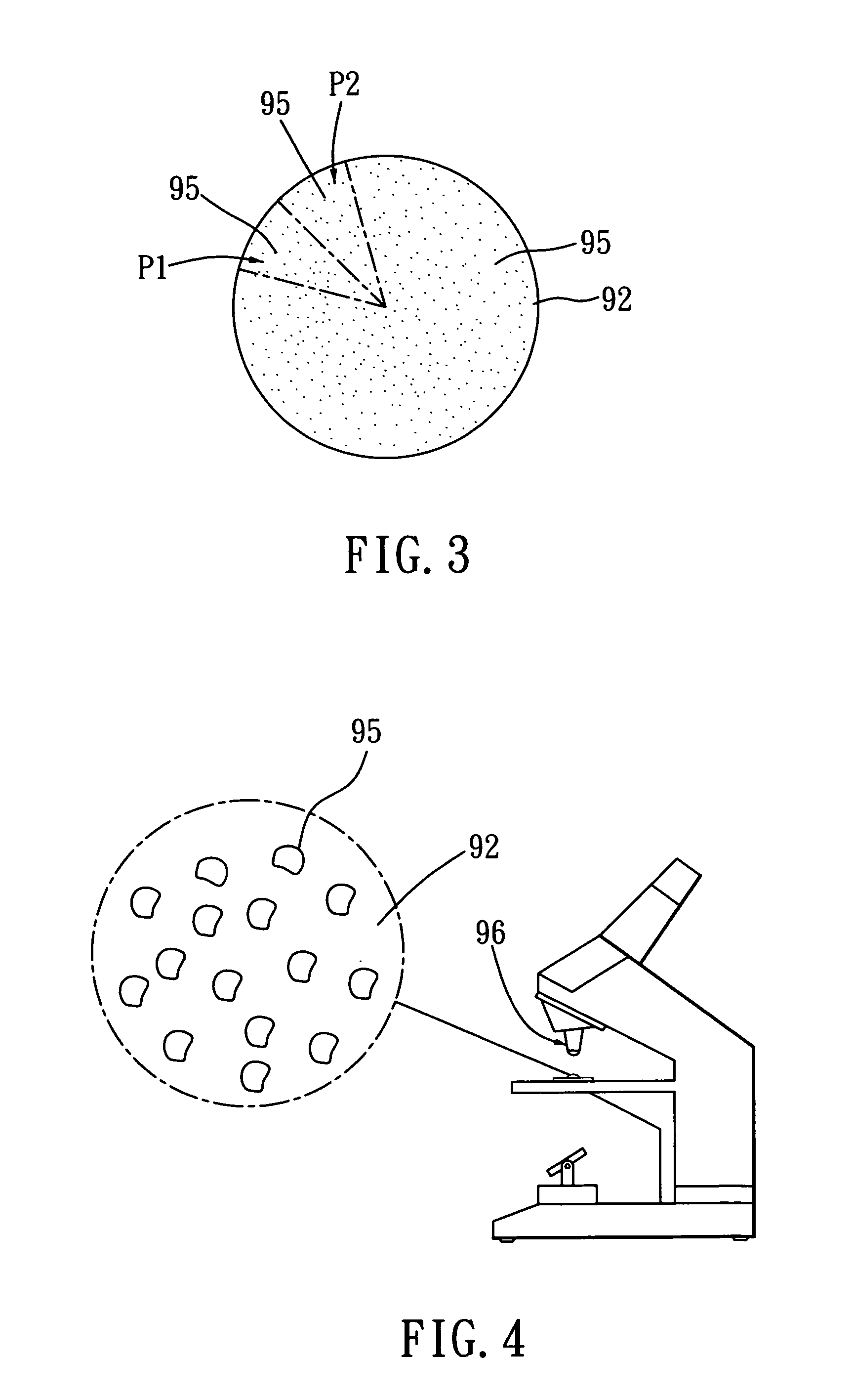
However, the aerosol concentrations in different zones of the filter media 92 are quite different, so it is very hard to evaluate the aerosol amount precisely.
The result will be inaccurate.
It is troublesome to count or evaluate the aerosol amount.

Method used


Image

  • Uniform aerosol deposit sampling device
  • Uniform aerosol deposit sampling device
  • Uniform aerosol deposit sampling device

Examples


Embodiment Construction

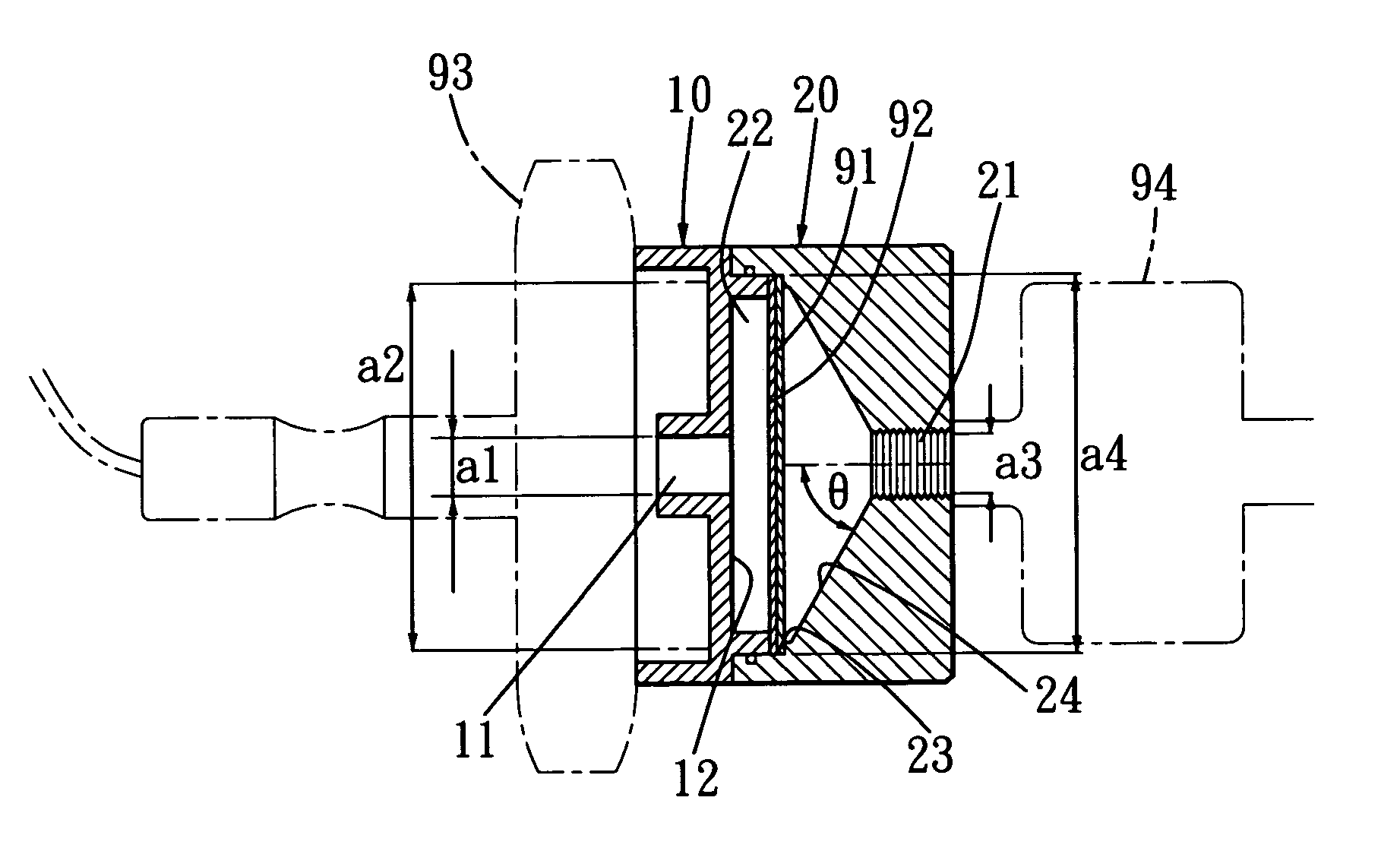
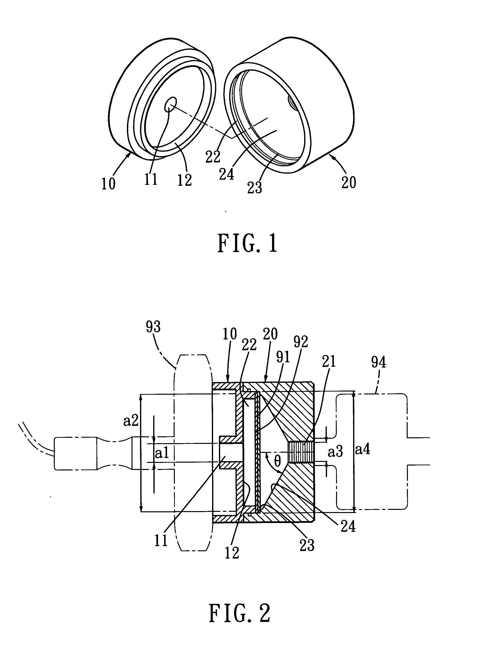
[0029]The present invention is a uniform aerosol deposit sampling device as shown in FIGS. 1 and 2. It comprises a first housing 10 and a second housing 20.

[0030]With regard to the first housing 10, it has an air inlet 11 and a first chamber 12. The air inlet 11 connects with this first chamber 12. The air inlet 11 has an air inlet cross-sectional area a1. The first chamber 12 has a first chamber cross-sectional area a2. The air inlet cross-sectional area a1 is smaller than the first chamber cross-sectional area a2.

[0031]About the second housing 20, it includes an air outlet 21, a second chamber 22, a filter holder 23 and a flow guiding portion 24. The air outlet 21 has an air outlet cross-sectional area a3. The air outlet 21 communicates with the flow guiding portion 24. This second chamber 21 connects with the first chamber 12. The second chamber 21 has a second chamber cross-sectional area a4. The second chamber cross-sectional area a4 is larger than the air outlet cross-sectiona...


PUM

PropertyMeasurementUnit
Angleaaaaaaaaaa
Compositionaaaaaaaaaa
Flow rateaaaaaaaaaa

Abstract

A uniform aerosol deposit sampling device includes a first housing and a second housing. The first housing has an air inlet and a first chamber. The second housing has an air outlet, an second chamber, a filter holder and a flow guiding portion. The filter holder is provided for securing an air-penetratable supporting pad and a filter media. The flow guiding portion is a substantially conical and gradually narrowing. The flow guiding portion has a semi-conical angle ranged from 15 to 85 degrees. So, the flow guiding portion makes the entire air flow smooth and evenly distributed. The aerosols will be evenly distributed and uniformly deposited on the filter media. And, it is easy to evaluate the amount and composition of the aerosols.

Description

BACKGROUND OF INVENTION[0001]1. Field of the Invention[0002]The present invention relates to a uniform aerosol deposit sampling device. In which, the flow guiding portion makes the entire air flow smooth and evenly distributed. The aerosols will be evenly distributed and uniformly deposited on the filter surface. And, it is easy to evaluate the amount and composition of the aerosols.[0003]2. Description of the Prior Art[0004]Referring to FIGS. 7 and 8, a typical conventional atmospheric aerosol sampling device comprising:[0005]a first body 81 including a first connecting portion 811 and a fist through-hole 812;[0006]a second body 82 including:[0007]a second connecting portion 821 for allowing the second body 82 and the first connecting portion 811 be connected together;[0008]a first-staged flow guiding portion 822 disposed in the second body 82, the first-staged flow guiding portion 822 having an air-penetratable supporting pad 91 and a filtering media 92;[0009]a second-staged flow ...

Claims


Application Information

Patent Timeline
IPC IPC(8): B01D46/00
CPCB01D46/0041
Inventor LAI, CHANE-YUTSAI, PERNG-JYTANG, DA TOUNGSHIH, TUNG-SHENGLEE, HSIN-YINGLEE, WAM YU
Owner INST OCCUPATIONAL SAFETY & HEALTH COUNCIL LABOR AFFAIRS EXECUTIVE YUAN
Learn More