Pressure Reducing Vavle

a vavle and pressure reduction technology, applied in the direction of valves, functional valve types, valve operating means/releasing devices, etc., can solve the problems of obstructive sleep apnea syndrome (osas), prone to narrow airways and/or collapse, and the pressure gradient between the lungs and the exterior of the body is not constan

Active Publication Date: 2008-04-03
RIC INVESTMENTS LLC
View PDF13 Cites 71 Cited by
  • Summary
  • Abstract
  • Description
  • Claims
  • Application Information

AI Technical Summary

Benefits of technology

[0013]According to another aspect of the present invention, in a system adapted to provide a regimen of respiratory therapy to a patient by providing a flow of breathing gas via a patient circuit including a pressure reducing valve with a first exhaust port and a second exhaust port therein, a method comprises delivering the flow of breathing gas to the airway of such a patient through the patient circuit during an inspiratory phase and diverting the flow of breathing gas away from the airway of such a patient through the first exhaust port while disposing of a flow of exhalation gas from the airway of such a patient through the second exhaust port during an expiratory phase.
[0014]According to another aspect of the present invention, an apparatus for delivering a flow of positive pressure gas to an airway of a patient comprises a gas flow generator structured to produce the flow of positive pressure gas, a patient interface device structured to communicate the flow of positive pressure gas to the airway of such a patient, and a patient circuit structured to couple the gas flow generator to the patient interface device, wherein the patient circuit includes a pressure reducing valv

Problems solved by technology

While sleeping, a patient suffering from obstructive sleep apnea syndrome (OSAS) is prone to having their airway narrow and/or collapse due to, for instance, mechanical collapsing forces that result from the structure of the airway tissues, muscle tone, and body position.
During a normal breathing cycle, however, the pressure gradient between the lungs and the exterior of the body is not constant.
Thus, although CPAP

Method used


Image

  • Pressure Reducing Vavle
  • Pressure Reducing Vavle
  • Pressure Reducing Vavle

Examples


Embodiment Construction

[0032]Directional phrases used herein, such as, for example, left, right, clockwise, counterclockwise, top, bottom, up, down, and derivatives thereof, relate to the orientation of the elements shown in the drawings and are not limiting upon the claims unless expressly recited therein.

[0033]As employed herein, the term “number” shall mean one or more than one and the singular form of “a”, “an”, and “the” include plural referents unless the context clearly indicates otherwise.

[0034]As employed herein, the statement that two or more parts are “connected” or “coupled” together shall mean that the parts are joined together either directly or joined together through one or more intermediate parts. Further, as employed herein, the statement that two or more parts are “attached” shall mean that the parts are joined together directly.

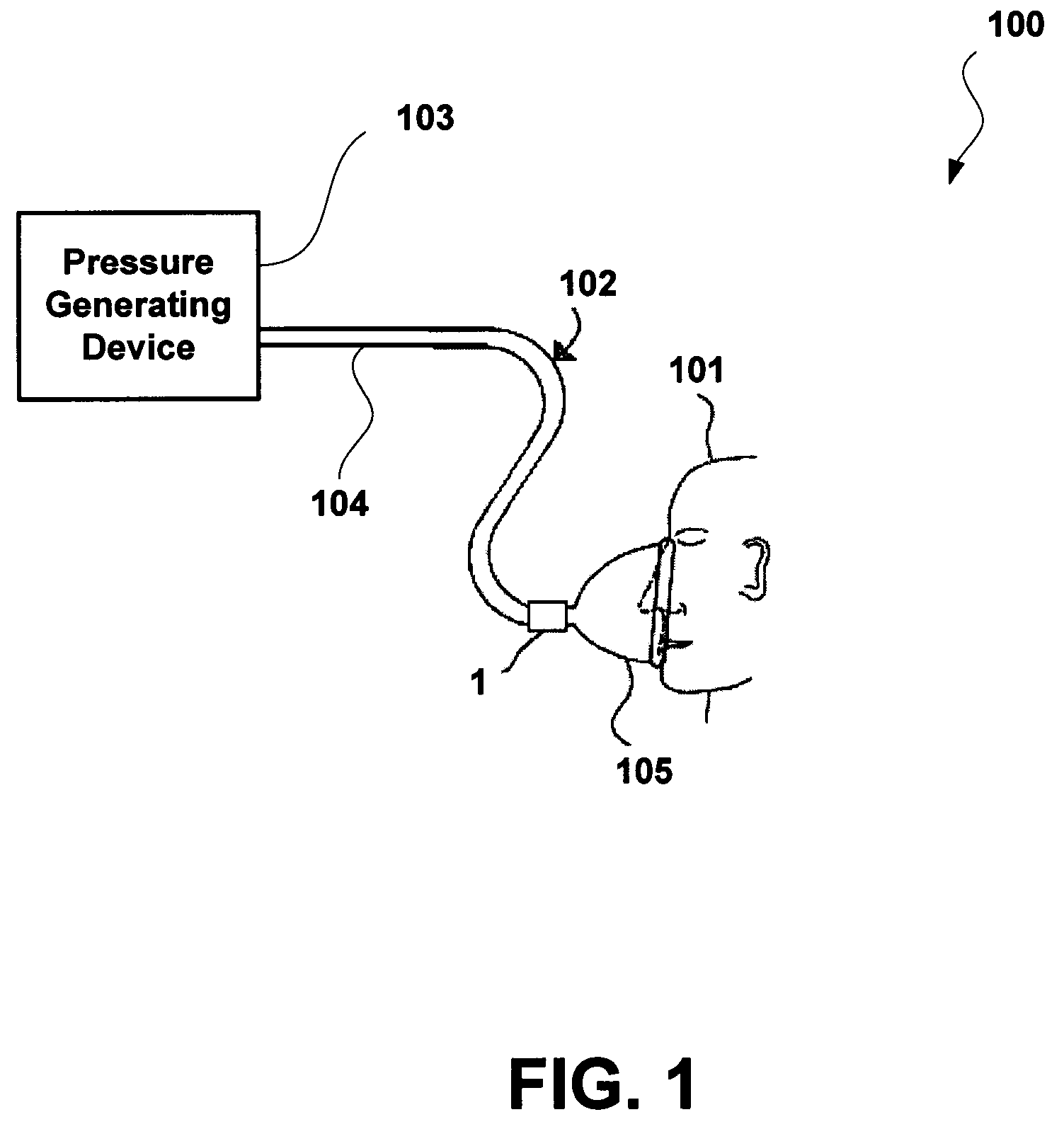
[0035]A system 100 adapted to provide a regimen of respiratory therapy to a patient 101 according to one embodiment is generally shown in FIG. 1. System 100 inc...


PUM


Abstract

A pressure reducing valve for use in a system adapted to deliver a breathing gas to a patient. The pressure reducing valve is structured to communicate a flow of breathing gas to such a patient's airway during an inspiratory phase. The pressure reducing valve is structured to isolate the flow of breathing gas from the patient's airway and to “dump” the flow of breathing gas and a flow of exhalation gas to atmosphere during the expiratory phase. The flow of breathing gas is dumped to atmosphere through a first number of ports; whereas a flow of exhalation gas is dumped to atmosphere through a second number of ports. Because the flow of breathing gas remains isolated from the flow of exhalation gas, less effort is required by a patient during the expiratory phase.

Description

CROSS-REFERENCE TO RELATED APPLICATIONS[0001]This application claims priority under 35 U.S.C. § 119(e) from provisional U.S. patent application No. 60 / 847,825 filed Sep. 28, 2006 the contents of which are incorporated herein by reference.BACKGROUND OF THE INVENTION[0002]1. Field of the Invention[0003]The present invention pertains to the delivery of a flow of breathing gas to the airway of a patient and more particularly to an apparatus and method for providing improved comfort for a patient receiving a flow of breathing gas.[0004]2. Description of the Related Art[0005]There are numerous situations where it is necessary or desirable to deliver a flow of breathing gas to the airway of a patient. For example, it is known to deliver a flow of breathing gas to a patient during at least a portion of the breathing cycle to treat breathing and / or cardiac disorders such as obstructive sleep apnea syndrome, chronic obstructive pulmonary disease, congestive heart failure, and other respirator...

Claims


Application Information

Patent Timeline
IPC IPC(8): A62B9/02
CPCA61M16/208Y10T137/7879A61M16/206
Inventor HO, PETER CHI FAIPAUL, ZACHARY D.BUSCH, LANCESOFRANKO, RICHARD A.JAFFRE, MARCEL D.
Owner RIC INVESTMENTS LLC
Why Eureka
Try Eureka