Respiratory device measurement system

a technology for respiratory devices and measurement systems, applied in the field of respiratory devices, can solve problems such as adding to the total cost of the devi

Active Publication Date: 2006-12-21
PHILIPS RS NORTH AMERICA LLC
View PDF14 Cites 110 Cited by
  • Summary
  • Abstract
  • Description
  • Claims
  • Application Information

AI Technical Summary

Benefits of technology

[0010] These and other objects, features, and characteristics of the present invention, as well as the methods of operation and functions of the related elements of structure and the combination of parts and economies of manufacture, will become more apparent upon consideration of the following description and the appended claims with reference to the accompanying drawings, all of which form a part of this specification, wherein like reference numerals designate corresponding parts in the various figures. It is to be expressly understood, however, that the drawings are for the purpose of illustration and description only and are not intended as a definition of the limits of the invention. As used in the specification and in the claims, the singular form of “a”, “an”, and “the” include plural referents unless the context clearly dictates otherwise.

Problems solved by technology

While these sensors may enhance the accuracy of the determination of the pressure, flow and / or total volume of the breathable gas, they add to the total cost of the device.

Method used


Image

  • Respiratory device measurement system
  • Respiratory device measurement system
  • Respiratory device measurement system

Examples


Embodiment Construction

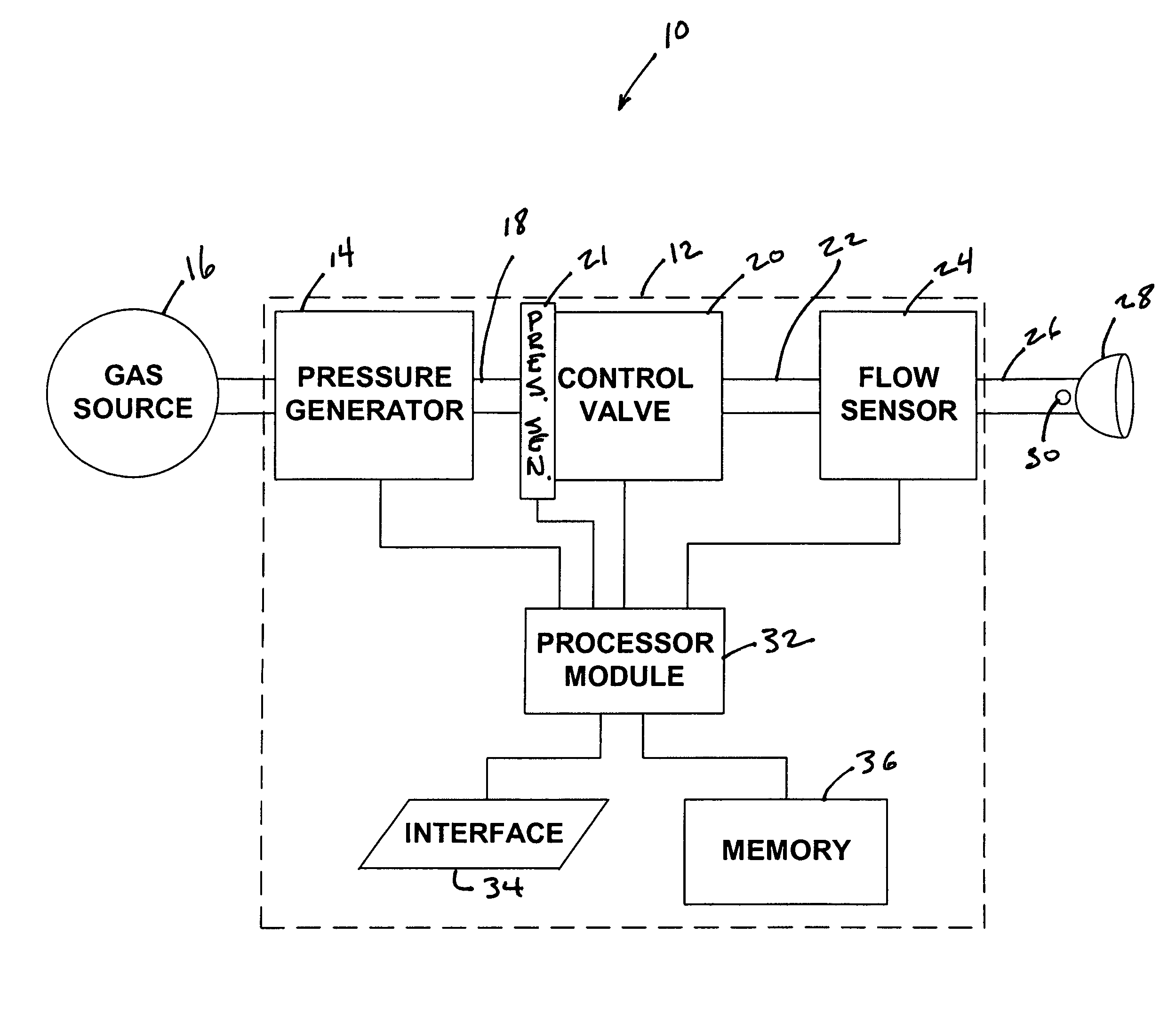
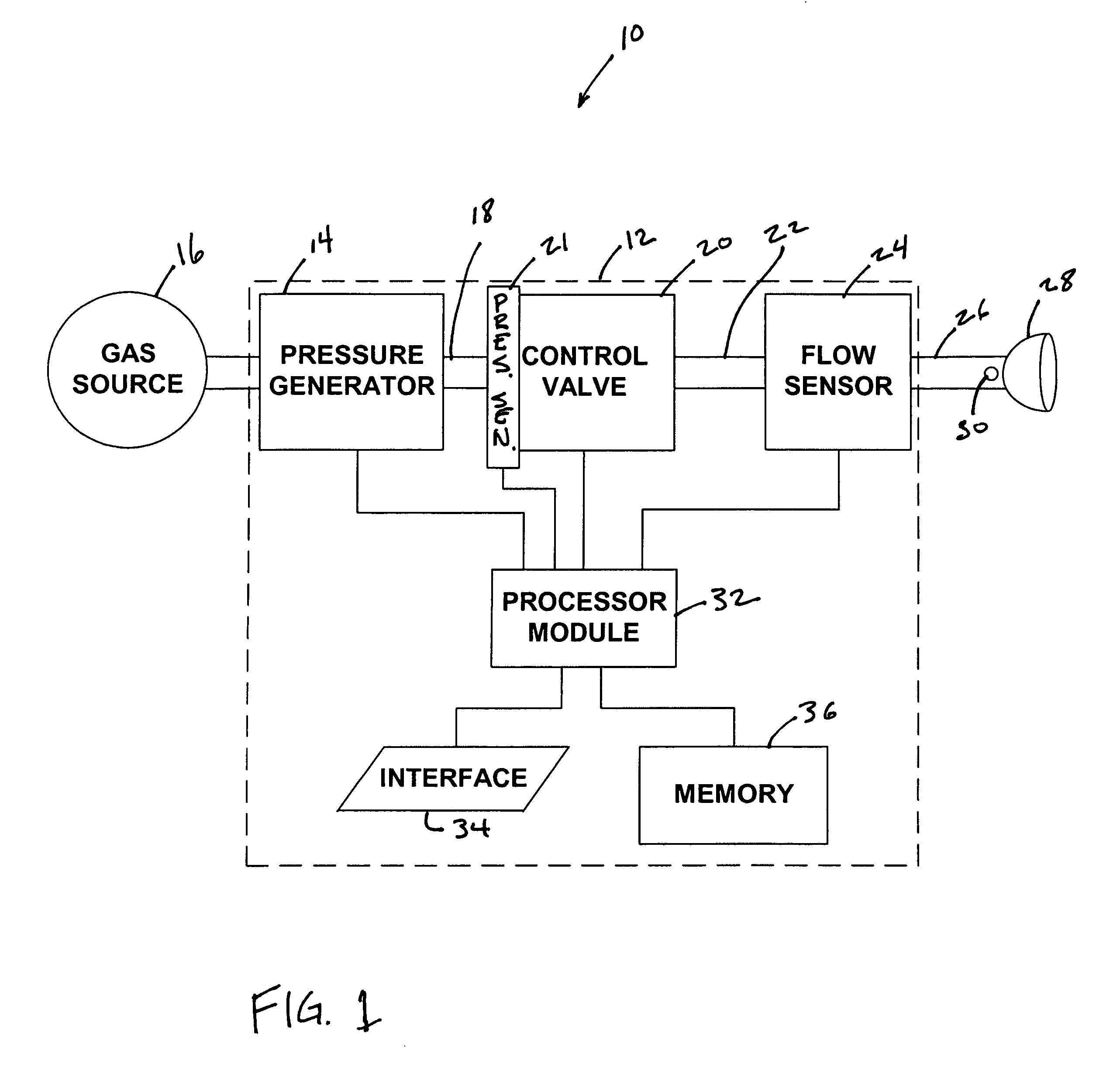
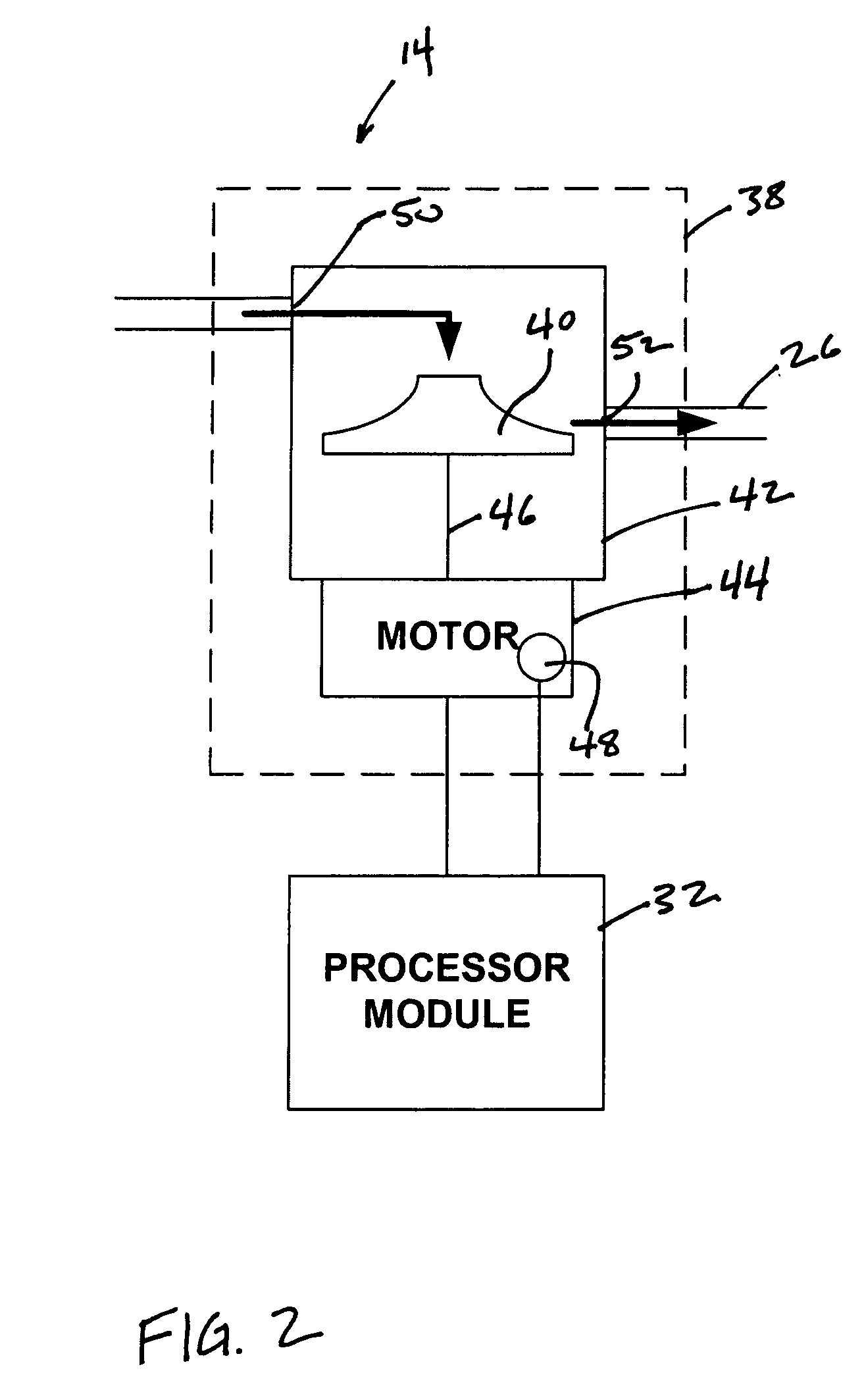
[0015]FIG. 1 schematically illustrates an exemplary first embodiment of a patient treatment system 10 according to the principles of the present invention. Patient treatment system 10 generally includes a gas delivery system 12. The gas delivery system 12 controls a flow of breathable gas to a patient and includes a pressure generator 14 that receives a supply of breathable gas from a gas source 16. The gas source 16, in one embodiment, is simply atmospheric air. Pressure generator 14 elevates the pressure of gas from gas source 16 for delivery to the airway of the patient.

[0016] In one embodiment of the present invention, pressure generator 14 comprises a blower, as will be described later in greater detail in connection with FIG. 2. The blower can optionally be driven at a constant speed during the course of the pressure support treatment to produce a constant pressure or flow rate at its output 18. The present invention also contemplates that breathing gas source 16 can be any s...


PUM


Abstract

A gas delivery system comprising a pressure generator, a pressure sensor, a control valve, and a processor. The pressure generator pressurizes breathable gas for delivery to a patient. The pressure sensor measures a pressure difference between the pressurized breathable gas and atmospheric pressure. The control valve is disposed downstream from the pressure generator and is constructed and arranged to control a flow rate of the pressurized breathable gas. The processor controls the control valve to bring the flow rate of the pressurized breathable gas to substantially zero while the pressure generator is operating and, when the flow rate is substantially zero, determines at least one of atmospheric pressure, an atmospheric air density, or a density correction factor based at least in part on the pressure difference between the pressurized breathable gas and the atmospheric pressure.

Description

CROSS-REFERENCE TO RELATED APPLICATIONS [0001] This application claims priority under 35 U.S.C. § 119(e) from provisional U.S. Patent Application No. 60 / 692,506 filed Jun. 21, 2005 the contents of which are incorporated herein by reference.BACKGROUND OF THE INVENTION [0002] 1. Field of the Invention [0003] The invention relates to respiratory devices. [0004] 2. Description of the Related Art [0005] Positive Airway Pressure (PAP) devices that deliver a pressurized flow of breathable gas to a patient are known. Typically, these PAP devices include a pressure generator that pressurizes the breathable gas, and one or more sensors for monitoring various parameters of the breathable gas and / or the ambient atmosphere. A PAP device usually uses the information received from the sensor(s) to control the pressure generator in a feedback loop to provide the breathable gas to the patient at a desired pressure and / or flow. The PAP device may also monitor the total amount of gas provided to the p...

Claims


Application Information

Patent Timeline
Patent Type & Authority Applications(United States)
IPC IPC(8): A61M16/00A62B7/00
CPCA61M16/0051A61M2205/3358A61M16/0075A61M2016/0021A61M2016/0039A61M2202/0208A61M2202/025A61M2202/0275A61M2205/3365A61M2205/3368A61M2205/3569A61M2205/52A61M2230/432A61M16/0063A61M16/0069A61M16/142A61M16/204A61M16/205A61M16/0066A61M2016/0033A61M16/0072A61B5/087A61B2560/0228G01F15/005G01F15/046A61M16/024A61B5/097A61B5/4836G01F25/10
Inventor SHISSLER, ANDREW L.TRUITT, PATRICK W.TRUSCHEL, WILLIAM A.
Owner PHILIPS RS NORTH AMERICA LLC
Why Eureka
Try Eureka