Carbon dioxide gas removal from a fluid circuit of a dialysis device

a dialysis device and fluid circuit technology, applied in the field of hemodialysis, to achieve the effect of efficient venting or removal of carbon dioxid

Inactive Publication Date: 2011-10-11
FRESENIUS MEDICAL CARE HLDG INC
View PDF23 Cites 112 Cited by
  • Summary
  • Abstract
  • Description
  • Claims
  • Application Information

AI Technical Summary

Benefits of technology

[0005]It is an object of the present invention to provide a degassing device that efficiently vents or removes carbon-dioxide, and other gas, bubbles, from dialysate circuit, that are produced from urea split by urease in the sorbent system of a dialysis device.
[0006]It is also an object of the present invention to have a degassing device that is particularly suitable for a portable hemodialyzer, such as one configured as a portable artificial kidney (PAK), where the orientation of the dialyzer should not disrupt or degrade the efficiency of the degassing device.
[0007]Accordingly, it is another object of the present invention the degassing device needs to be small in size, light and low cost so that it can be a disposable component.

Problems solved by technology

While the upper end of the inner housing is open, the upper end of the outer housing is sealed with a microporous, hydrophobic membrane that allows gases to pass through but does not allow liquids to pass.

Method used


Image

  • Carbon dioxide gas removal from a fluid circuit of a dialysis device
  • Carbon dioxide gas removal from a fluid circuit of a dialysis device
  • Carbon dioxide gas removal from a fluid circuit of a dialysis device

Examples


performance example 1

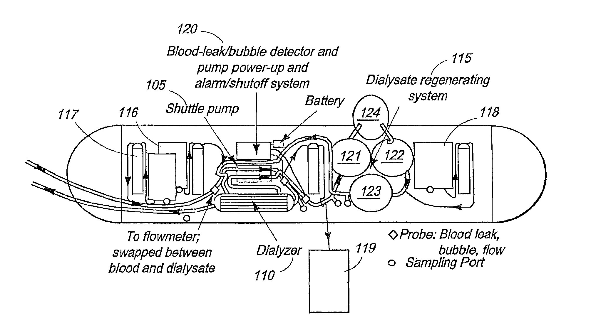
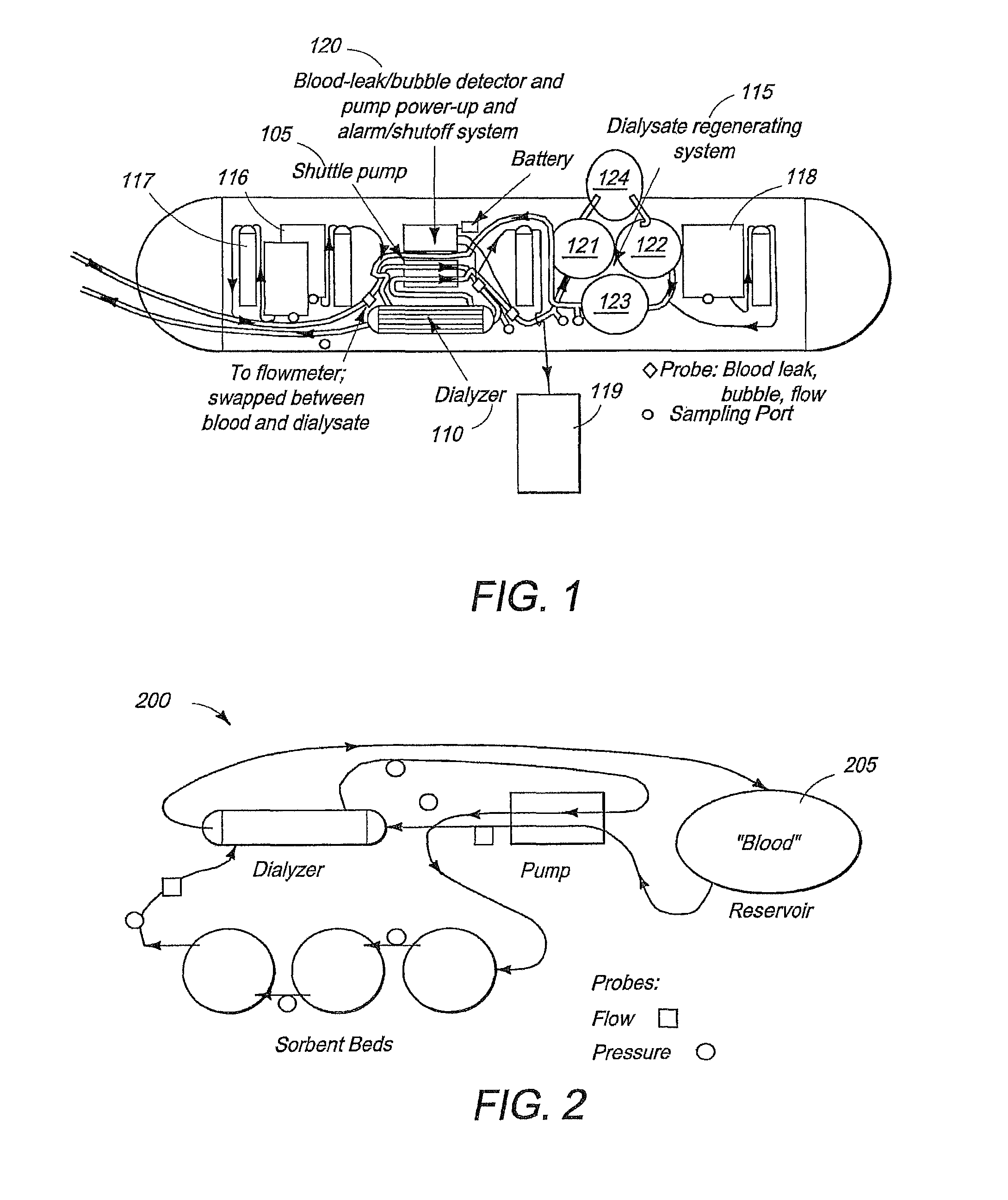
[0040]Various configurations of the dialysis device 100 of FIG. 1 were tested to evaluate their operational performance and, in particular, the gas removal capability of the degassing device 124 and 520. Referring to FIG. 2, after priming the dialysis device with saline, the dialysis device 200 was connected to a large (40- to 80-liter) reservoir 205 of properly formulated aqueous solution (referred to as “blood” here, made out of fresh deionized water or spent human dialysate) accurately mimicking end stage renal disease (ESRD) typical human blood. This “blood” was designed to approximate actual human composition and contained about 50 mg / dL of BUN (Blood Urea-Nitrogen), 10 mg / dL of creatinine, 5 mmol / L of K, among other solutes. No additives were provided and no ultrafiltration was performed; however, dialysate pH was maintained at an optimal value by a manual injection of sodium bicarbonate in order to measure its effect on the volume of CO2 produced. “Blood” and dialysate sample...


PUM

PropertyMeasurementUnit
flow ratesaaaaaaaaaa
thickaaaaaaaaaa

Abstract

The present invention is directed to degassing devices for dialysate circuits. One embodiment has a first housing and a second housing positioned within the first housing in an annular relationship. A second embodiment comprises a dialysate regeneration system with urease, a dialyzer, and a housing with an external wall, where the external wall is exposed to atmosphere and comprises a material that passes gas but does not pass liquid and where the housing is positioned between the urease and dialyzer.

Description

CROSS-REFERENCE[0001]The present application relies on U.S. Provisional Application No. 61 / 021,965, filed on Jan. 18, 2008, for priority and is herein incorporated by reference.FIELD OF THE INVENTION[0002]The present invention generally relates to the field of hemodialysis, and more specifically to a method and system of efficiently removing carbon dioxide, or any gas, from the dialysate circuit of a dialysis system without compromising the solute-removal performance of a hemodialysis device.BACKGROUND OF THE INVENTION[0003]Closed loop multi-pass sorbent based hemodialyzers have the advantage of being portable and compact while being able to regenerate dialysate using a plurality of sorbents. Typically these sorbents are used in disposable cartridges / canisters and comprise sorbent composition layers similar to those used in prior systems, such as urease, zirconium phosphate, hydrous zirconium oxide and activated carbon. As spent dialysate comprising urea, diffused from impure blood ...

Claims


Application Information

Patent Timeline
Patent Type & Authority Patents(United States)
IPC IPC(8): B01D53/22B01D19/00
CPCB01D19/0031A61M1/1658A61M1/1696A61M2205/75
Inventor GURA, VICTOREZON, CARLOS JACOBOBEIZAI, MASOUD
Owner FRESENIUS MEDICAL CARE HLDG INC
Why Eureka
Try Eureka