
Semi-closed brayton cycle gas turbine power systems

Inactive Publication Date: 2002-02-28
CLEAN ENERGY SYST
View PDF0 Cites 105 Cited by
  • Summary
  • Abstract
  • Description
  • Claims
  • Application Information

AI Technical Summary

Benefits of technology

[0025] Accordingly, a primary object of the present invention is to provide a Brayton cycle gas turbine power system which does not emit NO.sub.x or other pollutants, and which efficiently collects CO.sub.2 for beneficial use or elimination.
[0027] Another object of the present invention is to provide a process for modifying an open Brayton cycle gas turbine to function as a semi-closed Brayton cycle gas turbine power system which substantially eliminates emission of pollutants.
[0028] Another object of the present invention is to provide substantially nitrogen free air substitute working fluids which can operate within a Brayton cycle gas turbine without significantly altering the performance of the gas turbine and eliminate pollutant emissions from the gas turbine.
[0029] Another object of the present invention is to provide a power system which can efficiently generate power from the combustion of hydrocarbon fuels without emission of pollutants.
[0030] Another object of the present invention is to provide a semi-closed gas turbine power system with steam injection to enhance the power output and, efficiency of the power system.

Problems solved by technology

While significant advances in compressor and turbine designs have greatly increased the efficiency with which the gas turbine operates and have increased the temperature at which the gas turbine can operate, the gas turbine has certain drawbacks.
One drawback of the open Brayton cycle gas turbine is that the exhaust includes oxides of nitrogen (NO.sub.x).
Such "scrubbers" not only decrease the efficiency of the operation of the gas turbine, they are costly and also fail to remove all of the NO.sub.x from the exhaust.
While renewable non-polluting heat sources such as nuclear, solar and geothermal are effective, they suffer from drawbacks which have limited their ability to be fully competitive with hydrocarbon fuel combustion powered gas turbine systems.
While such CO.sub.2 closed Brayton cycle gas turbine systems do keep nitrogen out of the combustor and so do not produce NO.sub.x, the high density of CO.sub.2 makes it ill suited for use within a compressor which has been designed for compression of air.
Steam injection open Brayton cycles also suffer from numerous drawbacks.
Water purification costs hence impede the desirability of prior art steam injection open Brayton cycles.

Method used


Image

  • Semi-closed brayton cycle gas turbine power systems
  • Semi-closed brayton cycle gas turbine power systems
  • Semi-closed brayton cycle gas turbine power systems

Examples


example 2

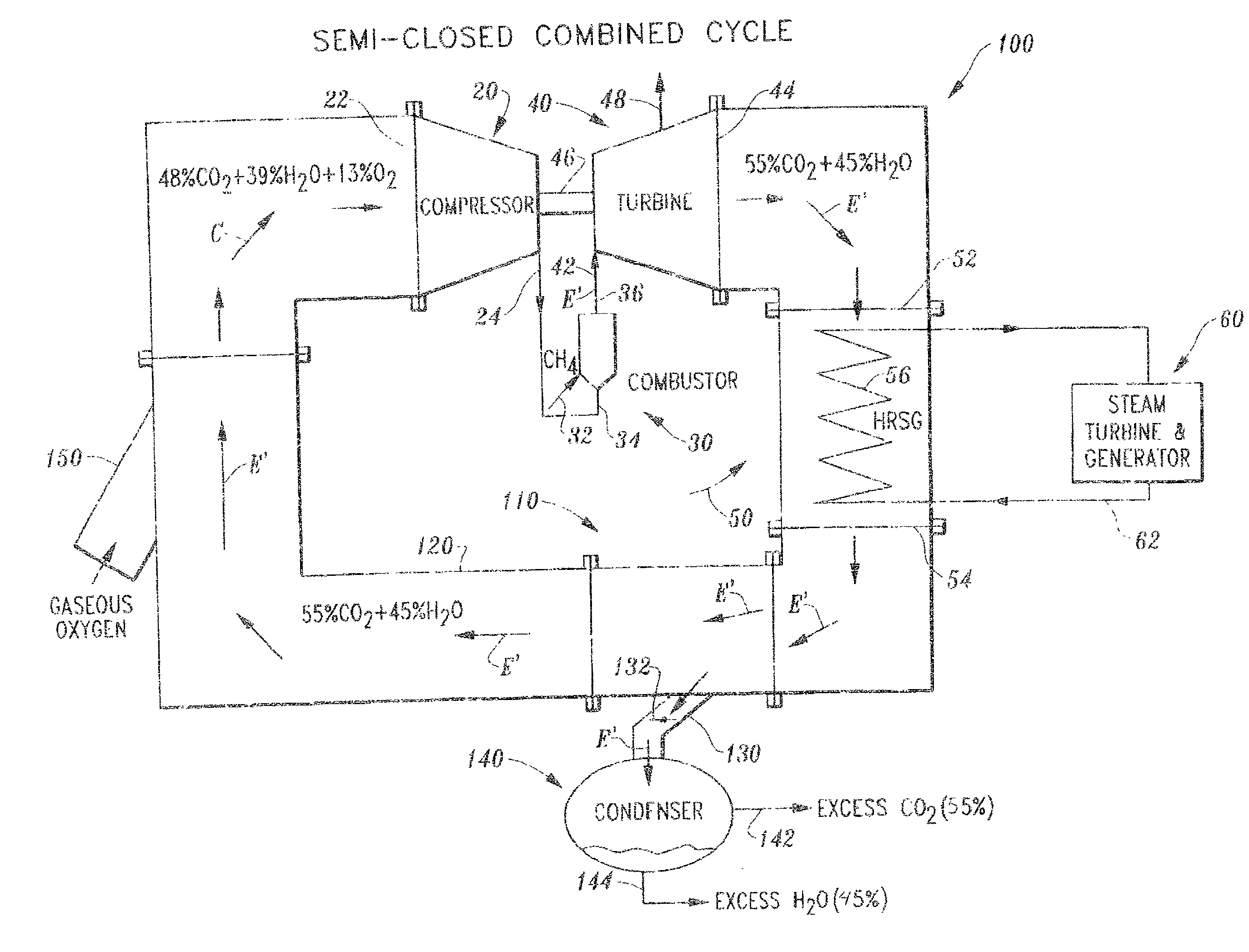
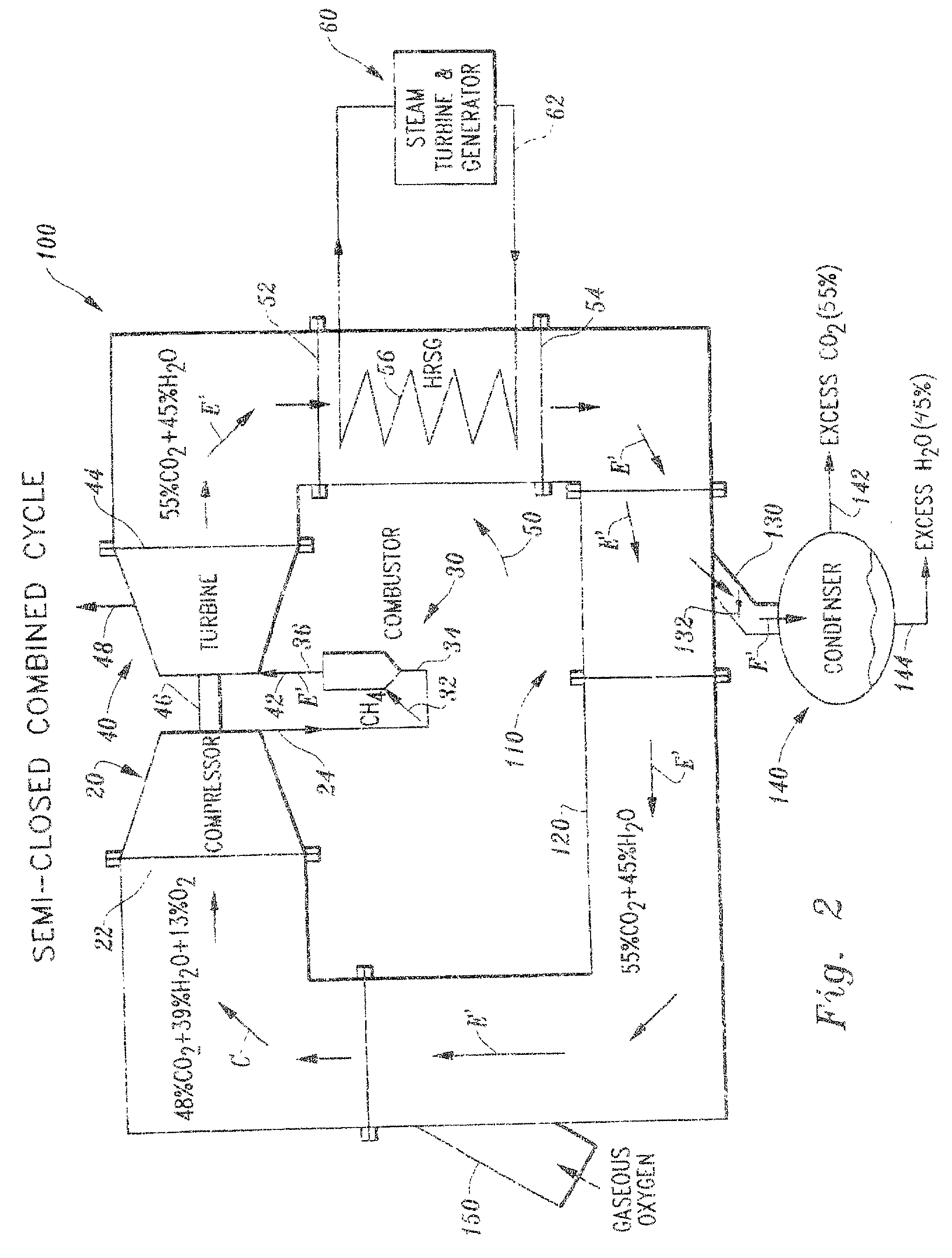
[0106] In this example, a little over half of the steam is condensed within the partial condenser 210. Specifically, the CO.sub.2-enriched exhaust E" exiting the partial condenser 210 includes 79% wt CO.sub.2 and 21% wt steam. Oxygen is supplied by the oxygen duct 150 at a ratio to the CO.sub.2-enriched exhaust E" to produce the gas mixture C' including 63% wt CO.sub.2, 17% wt steam and 20% wt oxygen. This gas mixture C' has air mimicking attributes similar to those of the gas mixture C of the previous embodiment (FIG. 2). Hence, the compressor 20 can compress the gas mixture C' while operating within its design parameters for the compression of air A (FIG. 1).

[0107] Note that the gas mixture C' includes 20% wt oxygen which is approximately the amount of oxygen within air A. This gas mixture C' can be utilized as the oxidizer within the combustor with an amount of fuel similar to that utilized when the combustor 30 is burning the fuel, such as natural gas or methane, in air A (FIG. ...


PUM


Abstract

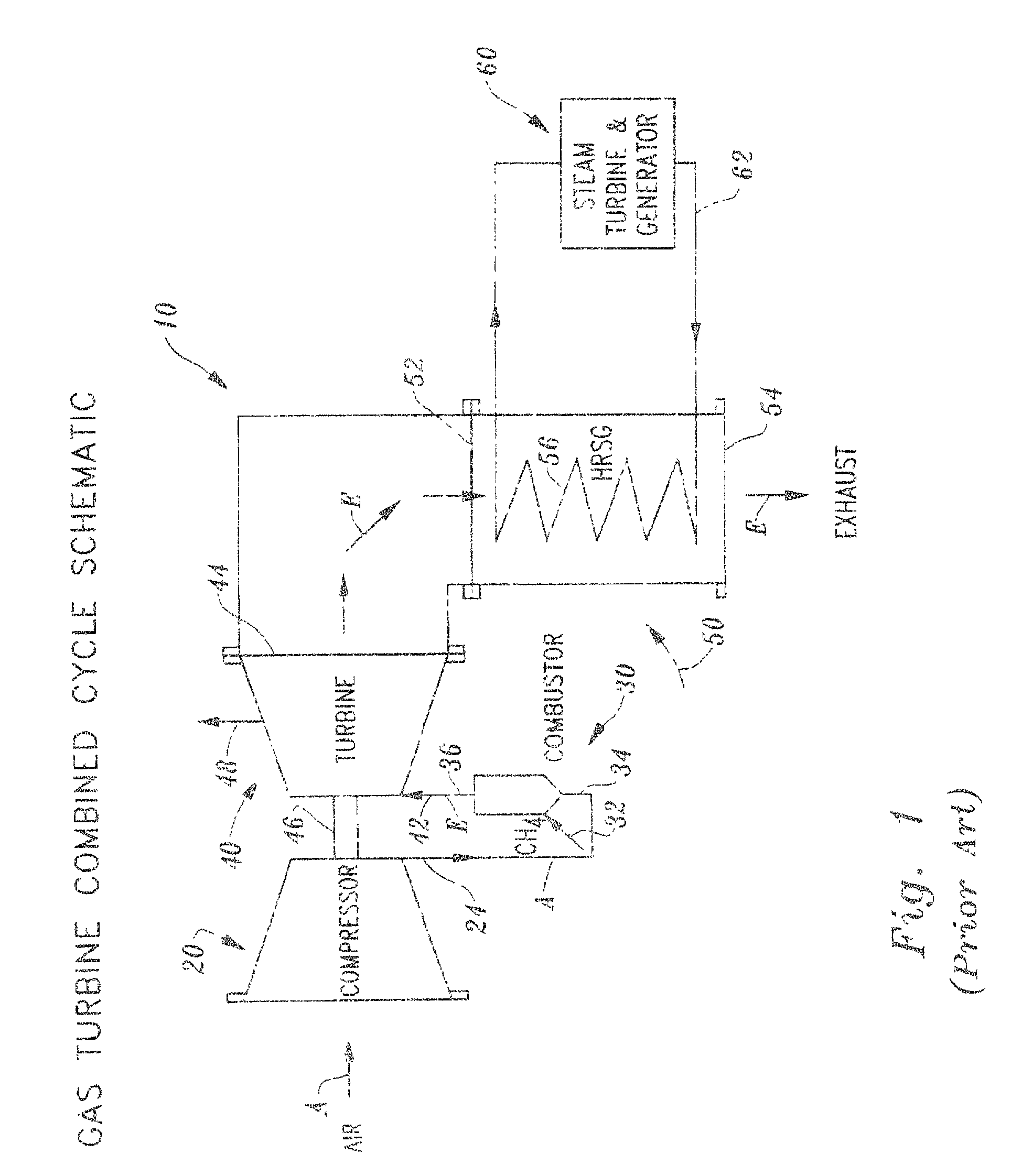
A semi-closed combined cycle power system 100 is provided which can also convert an open combined cycle gas turbine 10 into a non-polluting zero emissions power system. The prior art open combined cycle gas turbine 10 includes a compressor 20 which compresses air A' and combusts the air A' with a fuel, such as natural gas. The products of combustion and the remaining portions of the air form the exhaust E' which is expanded through the turbine 40. The turbine 40 drives the compressor 20 and outputs power. The exhaust E' exits the turbine 40 and then can optionally be routed through a heat recovery steam generator 50 to function as a combined cycle. According to this invention, the exhaust E' is not emitted into the atmosphere, but rather is routed to a divider 110. The divider 110 includes two outlets for the exhaust E' including a return duct 120 and a separation duct 130 which both receive a portion of the exhaust E'. The return duct 120 routes a portion of the exhaust E' back to the compressor 20. Before reaching the compressor 20, an oxygen duct 150 adds additional oxygen to the exhaust E' to form a gas mixture C which includes CO2 and steam from the exhaust E' and oxygen from the oxygen duct 150. This gas mixture C has characteristics which mimic those of air, so that the compressor 20 need not be modified to effectively compress the gas mixture C. The gas mixture C is compressed within the compressor 20 and routed to the combustor 30 where the fuel combusts with the oxygen of the gas mixture C' and produces exhaust E' which is substantially entirely CO2 and steam. This exhaust E' is routed through the turbine 40 and expanded to drive the compressor 20 and output power. The exhaust E' exits the turbine 40 and is routed back to the divider 110, preferably by way of a heat recovery steam generator 50 or other heat removal device, so that the semi-closed cycle operates as a combined cycle power system 100. The divider 110 directs a portion of the exhaust E' to a separation duct 130 which leads to a condenser 140. In the condenser 140 the exhaust E' is separated by condensation of the steam / water portion of the exhaust and removal of the remaining CO2 as gas from the condenser 140. The only exhaust from the semi-closed power system 100 is water and CO2 from the condenser. The CO2 exhaust is substantially pure and ready for appropriate further handling and disposal. Hence, no pollutants are emitted from the semi-closed power system 100. The return duct 120 can

Description

[0001] The following invention relates to Brayton cycle power generation systems which include a gaseous working fluid which is compressed, heated and expanded to generate power. More particularly, this invention relates to a semi-closed Brayton cycle power system which includes a gas turbine operating on a working fluid which is partially recirculated, the system eliminating emission of pollutants and emitting carbon dioxide in an easily separated and recoverable form.[0002] Gas turbine power systems have become popular systems for meeting modern society's power needs. Not only do gas turbines provide thrust for most large aircraft, but they also have been adapted for use in generation of electricity in stationary power plants.[0003] Gas turbines operate on the Brayton cycle and have a working fluid, typically air, which remains gaseous throughout the cycle. While the Brayton cycle can theoretically be closed so that the working fluid recirculates, the vast majority of operational ...

Claims


Application Information

Patent Timeline
IPC IPC(8): F01K21/04F01K23/10F02C1/00F02C1/08F02C3/20F02C3/34F02C6/18
CPCF01K21/047F01K23/10F02C1/007F02C1/08F02C3/20F02C3/34F02C6/18Y02E20/16Y02T50/671F05D2220/72F23L7/005Y02E20/32Y02E20/34Y02P80/15Y02T50/60
Inventor VITERI, FERMINANDERSON, ROGER E.
Owner CLEAN ENERGY SYST
Learn More