

Method for multiplexing control signals and reference signals in mobile communications system
a mobile communication system and control signal technology, applied in the field of mobile communication system, can solve the problems of limiting the number of sequences that can be obtained, the limit of the number of ues that can be multiplexed by cdm with respect to reference signal, and the inability to allocate a resource for reference signal
- Summary
- Abstract
- Description
- Claims
- Application Information
AI Technical Summary
Benefits of technology
Problems solved by technology
Method used
Image

Examples
first exemplary embodiment
4. First Exemplary Embodiment
[0086]According to the first exemplary embodiment of the present invention, resource allocation is performed by a base station such that among control signals for multiple UEs, control signals having the same bandwidth are multiplexed by DFDM, and reference signals for those UEs corresponding to the DFDM control signals are multiplexed by CDM over the total bandwidth of the DFDM control signals.
[0087]Specifically, the resource allocation section 104 acquires information about past resource allocation, information about the presence or absence of downlink data to be sent to each UE, which is acquired from the scheduler performing downlink resource allocation, and the like. Based on these pieces of information, the resource allocation section 104 selects from among multiple types of control information having different amounts of information (here, “Ack / Nack” and “CQI”) one type or multiple types of control information (here, any one or both of “Ack / Nack” ...
example 1
4.1) EXAMPLE 1
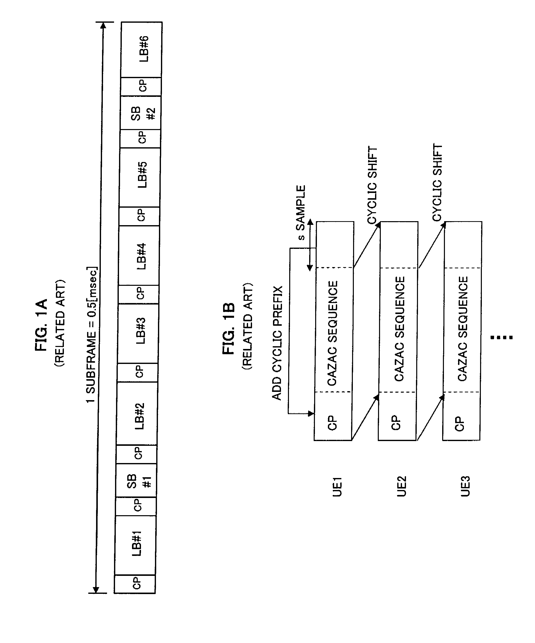
[0088]FIG. 9 is a diagram showing an example of the allocation of resources for control and reference signals according to the first exemplary embodiment of the present invention. Here, it is assumed that control and reference signals are multiplexed by time division multiplexing (TDM), and that in each sub-frame, data and control signals are transmitted in long blocks (LB) and reference signals are transmitted in short blocks (SB), as shown in FIG. 1A for example.
[0089]Specifically, referring to FIG. 9, UEs 1 and 6 are those transmitting both of Ack / Nack and CQI and are multiplexed by DFDM with a repetition factor of 2 over a bandwidth that is twice as wide as a bandwidth for transmitting Ack / Nack and CQI. With respect to reference signals for the UEs 1 and 6, the two UEs are multiplexed by CDM over the bandwidth that is twice as wide as the bandwidth for transmitting Ack / Nack and CQI.
[0090]UEs 2 and 3 are those transmitting Ack / Nack only and are multiplexed by DFDM w...
example 2
4.2) EXAMPLE 2
[0094]FIG. 10 is a diagram showing another example of the allocation of resources for control and reference signals according to the first exemplary embodiment of the present invention. Here, it is assumed that in each sub-frame, control signals are transmitted in a long block LB#1, reference signals are transmitted in short blocks SB#1 and SB#2, and data signals are transmitted in long blocks LB#2 to LB#6, as shown in the LTE's uplink frame format in FIG. 3.
[0095]When a data signal is transmitted in long blocks LB#2 to LB#6, a reference signal for demodulating the data signal is transmitted in each of short blocks SB#1 and SB#2. In the present example, in the short block SB#1, a reference signal for a UE 7, which transmits data, is multiplexed by DFDM with, for example, reference signals for control signals for UEs 1 and 6 that are multiplexed by CDM (the hybrid of FDM and CDM). In the short block SB#2, a reference signal for the UE7 is multiplexed by DFDM with a refe...
PUM
 Abstract
Description
Claims
Application Information