
Coordination of control operations in an optical network

a technology of optical network and control operation, applied in the field of optical communication system, can solve the problems of limiting the available network topologies, difficult to determine what constitutes a ring or a line, and increasing the arbitraryity of subdivisions, so as to reduce unfavorable interactions

Active Publication Date: 2008-04-03
ALCATEL-LUCENT USA INC
View PDF6 Cites 2 Cited by
  • Summary
  • Abstract
  • Description
  • Claims
  • Application Information

AI Technical Summary

Benefits of technology

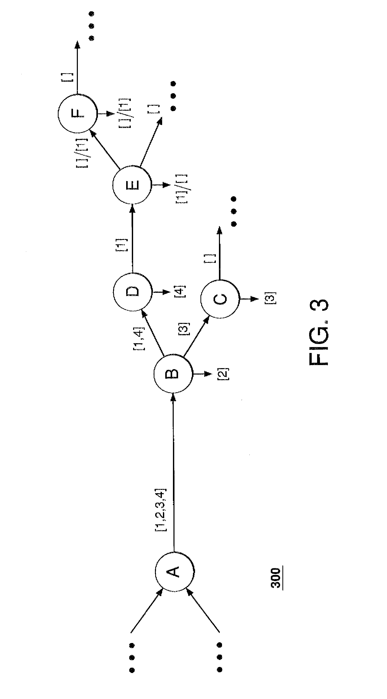
[0008]Problems in the prior art are addressed by embodiments of a control method, according to which a cascade of control messages is propagated between nodes of an optically transparent network, with each message being sent from a node to an adjacent downstream node to inform the latter about a control operation scheduled to be performed at the message-sending node and / or an upstream node that impacts an optical communication signal received at that downstream node. The cascade of control messages effectively creates an ad hoc control domain, in which control operations performed at various nodes of that domain can be coordinated to reduce unfavorable interactions between those control operations. By repeatedly propagating appropriate cascades of control messages through the network, control domains can be changed dynamically and adaptively to reflect any changes to the network topology, equipment, and / or traffic distribution.

Problems solved by technology

However, this approach limits the available network topologies.
In addition, for a network having a relatively complex topology, it might be difficult to determine what constitutes a ring or a line.
This difficulty might cause the subdivisions to become more and more arbitrary as the network complexity increases.
However, this approach complicates the network deployment because control domains have to be defined before the deployment and information about the control domains has to be provisioned at the nodes.
Disadvantageously, tracking and maintaining the integrity of that information can significantly increase the operational costs for the network.
An additional problem with using predefined control domains is that, in many cases, the optimal configuration of control domains might change when the network is expanded or otherwise reconfigured.
Because most control operations are sensitive to both the network's hardware and traffic distribution, both “hard” and “soft” changes need to be accounted for in the provisioned information, which further increases the operational costs.

Method used


Image

  • Coordination of control operations in an optical network
  • Coordination of control operations in an optical network
  • Coordination of control operations in an optical network

Examples


Embodiment Construction

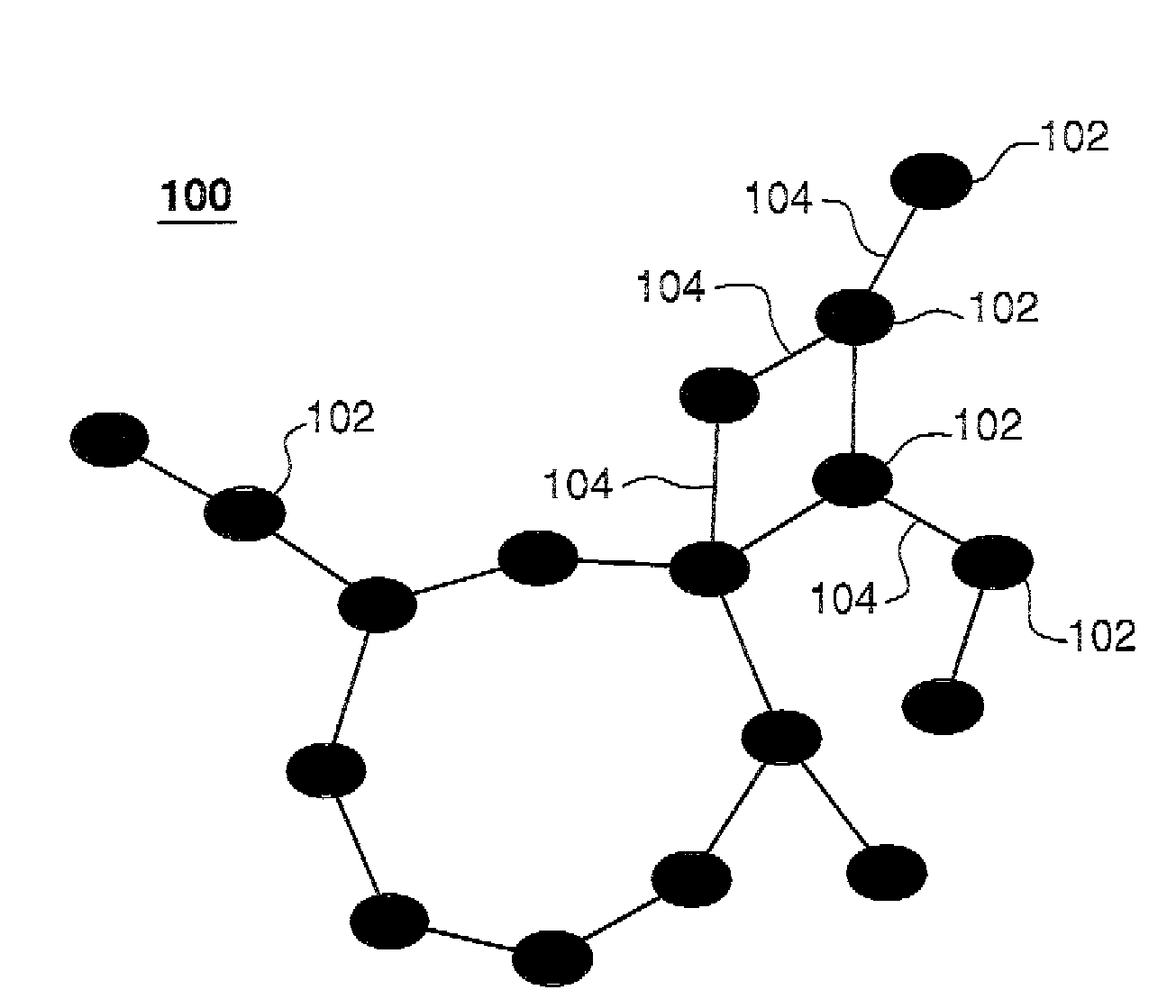
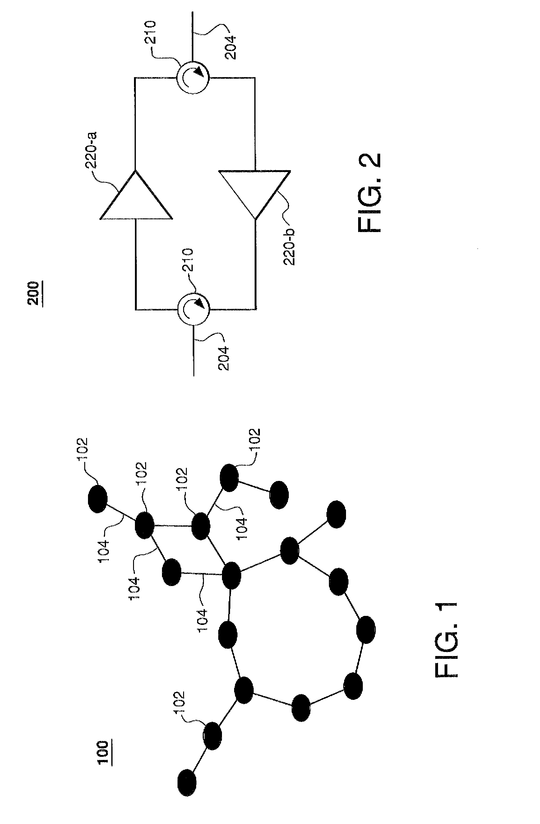
[0018]FIG. 1 shows an optically transparent network 100 according to one embodiment. Network 100 has a plurality of nodes 102 connected by a plurality of communication links 104 as indicated in FIG. 1. Each node 102 is adapted to send and / or receive optical communication signals via the corresponding communication links 104, with each communication link having an optical fiber configured to transmit optical communication signals in one or both directions. If node 102 is a source node for an optical signal, then that signal is added to the optical signals transmitted by the node and coupled into an appropriate communication link 104. If node 102 is a destination node for a received optical signal, then that signal is dropped at that node. If node 102 is a transit node for a received optical signal, then that signal is coupled into an appropriate communication link 104 for further transmission to the signal's destination node.

[0019]FIG. 2 shows an amplifier block 200 that can be used ...


PUM


Abstract

In one embodiment, a control method, according to which a cascade of control messages is propagated between nodes of an optically transparent network, with each message being sent from a node to an adjacent downstream node to inform the latter about a control operation scheduled to be performed at the message-sending node and / or an upstream node that impacts an optical communication signal received at that downstream node. The cascade of control messages effectively creates an ad hoc control domain, in which control operations performed at various nodes of that domain can be coordinated to reduce unfavorable interactions between those control operations. By repeatedly propagating appropriate cascades of control messages through the network, control domains can be changed dynamically and adaptively to reflect any changes to the network topology, equipment, and / or traffic distribution.

Description

BACKGROUND[0001]1. Field of the Invention[0002]The present invention relates to optical communications systems and, more specifically, to optically transparent networks.[0003]2. Description of the Related Art[0004]An optically transparent network has a plurality of nodes connected by optical links and operated so that optical communication signals are transmitted from a source node, through one or more transit nodes (if any), to a destination node without being converted into electrical signals at any point along the way. A mesh network is a network in which, with the exception of nodes in certain terminal branches, two or more different communication paths exist for connecting any pair of nodes. Mesh networking is advantageous because, generally, it enables continuous connections and reconfiguration around blocked communication paths by hopping from node to node until a connection can be established.[0005]One approach to coordinating control operations performed at different nodes ...

Claims


Application Information

Patent Timeline
IPC IPC(8): H04B10/08H04B17/00
CPCH04B10/0773H04J14/0227H04J14/0278H04J14/0284H04L12/24H04J14/0241H04Q11/0062H04Q2011/0079H04Q2011/0088H04Q2011/0098H04L41/00
Inventor FELDMAN, ROBERT D.KILPER, DANIEL C.SKROBALA, THOMAS A.WHITE, CHRISTOPHER A.YU, LILI
Owner ALCATEL-LUCENT USA INC
Learn More