Connector

Inactive Publication Date: 2008-04-03
ORMON CORPORATION
View PDF1 Cites 9 Cited by
  • Summary
  • Abstract
  • Description
  • Claims
  • Application Information

AI Technical Summary

Benefits of technology

[0006] With the above problems in view, it is an object of the present invention to provide a connector with

Problems solved by technology

In the above-described connector, however, a jig is necessary to mount the pressing cover 30 to t

Method used


Image

  • Connector
  • Connector
  • Connector

Examples


Example

[0027] An embodiment according to the present invention will be described based on the accompanying drawings (FIGS. 1A to 14C).

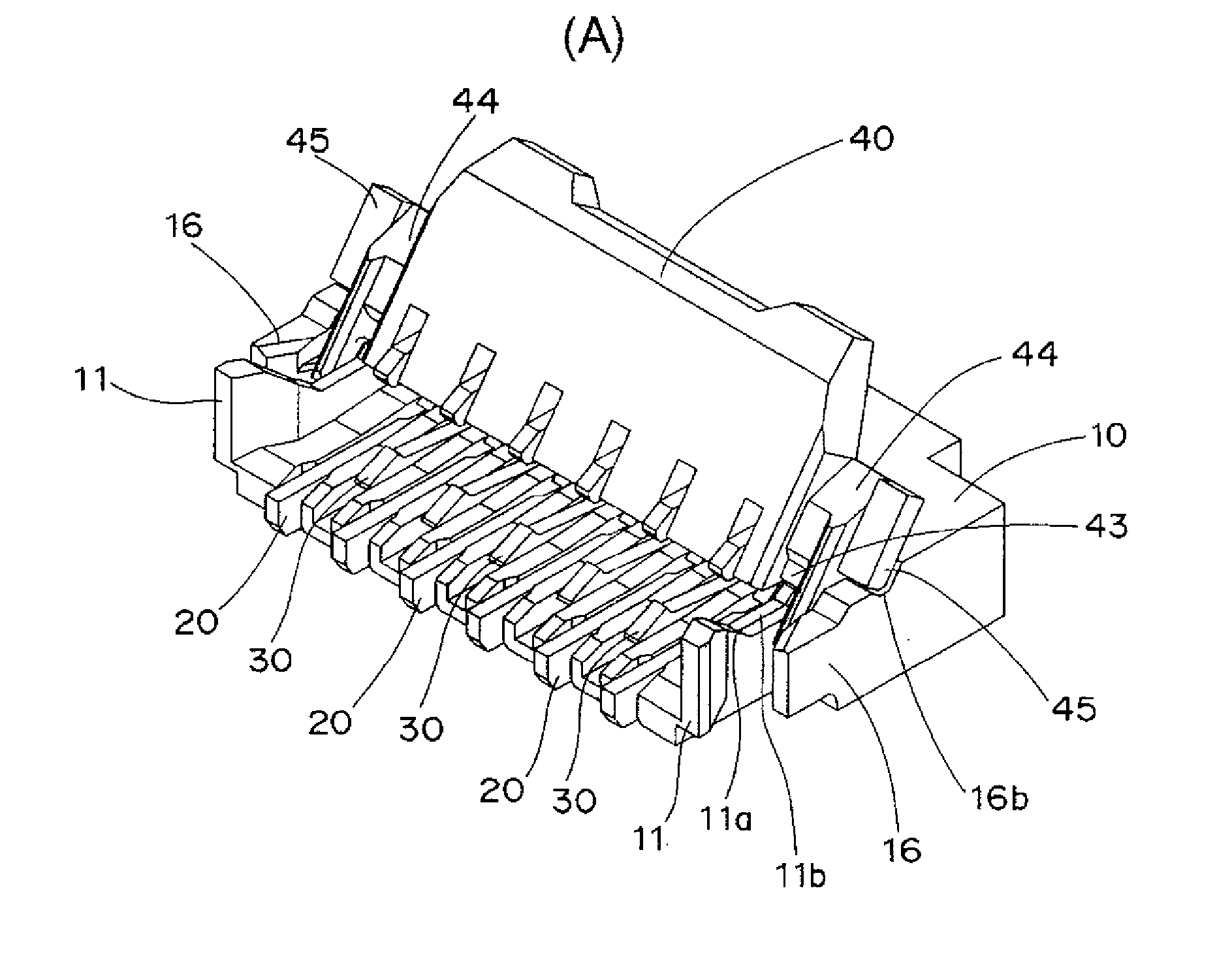
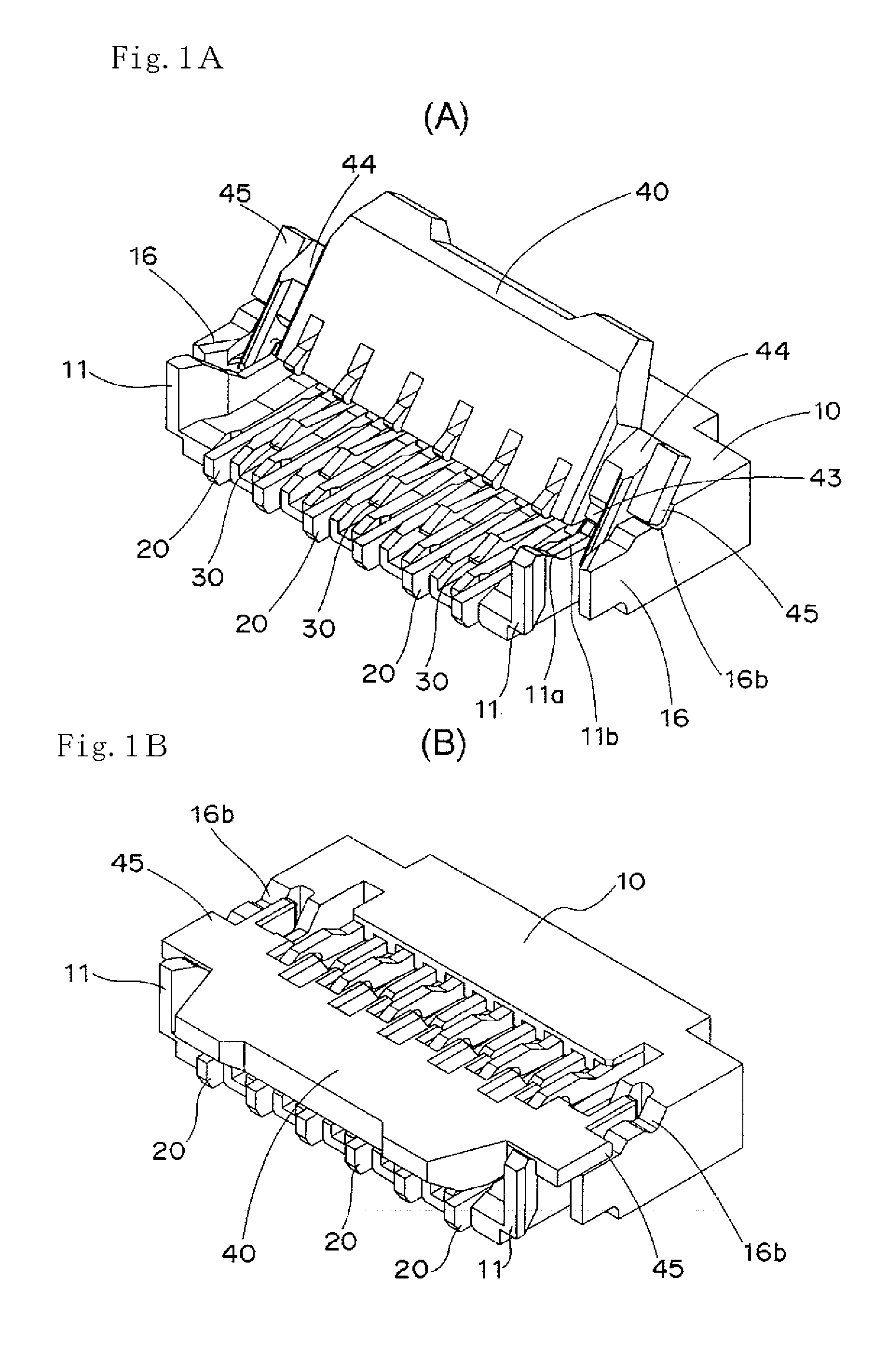
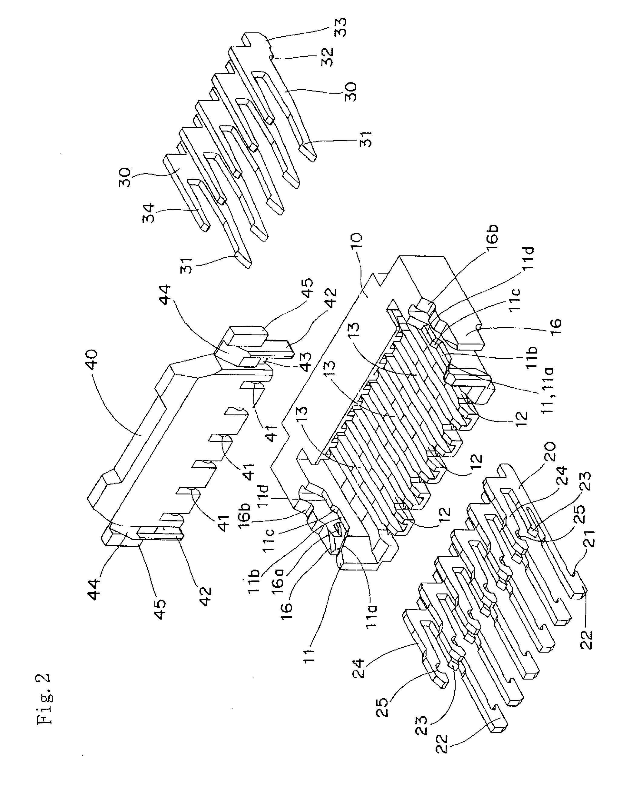
[0028] The connector according to the present embodiment is formed of a base 10, first connecting terminals 20, second connecting terminals 30, and an operating lever 40 as shown in FIGS. 1A to 2.

[0029] Dimensions of a connector embodying the present embodiment are 0.9 mm (height) by 3.5 mm (depth), and a pitch of adjacent connecting terminals is 0.3 mm.

[0030] In the base 10, first and second guide grooves 12, 13 are alternately arranged at a predetermined pitch between partition walls 11, 11 provided to protrude from opposite side end portions to face each other as shown in FIGS. 3A to 4. Tip end edge portions of the partition walls 11 are slightly open outward so as to facilitate insertion of a flexible board 50 which will be described later. Moreover, each of the partition walls 11 has a first tapered face 11a for preventing coming off at its upper end...


PUM


Abstract

A connector includes a base mounted with connecting terminals at a predetermined pitch and an operating lever turnably supported on the base. The operating lever presses and connects a tip end portion of a flexible printed circuit board against and to fixed contacts of the connecting terminals. Mounting protrusions provided to opposite end portions of the operating lever are moved along first slide faces, tapered faces, and second slide faces. The faces are formed in an uninterrupted manner on upper end faces of partition walls provided to opposite side end portions of the base. Turning shaft portions coaxially provided in an interrupted manner to remaining one side edge portion of the operating lever push up elastic finger portions of the connecting terminals. The turning shaft portions are turnably fitted in bearing recessed portions formed at the elastic finger portions.

Description

BACKGROUND OF THE INVENTION [0001] 1. Field of the Invention [0002] The present invention relates to a connector and particularly to a connector which is surface-mounted on a printed circuit board and to which a flexible printed circuit board (hereinafter referred to as “FPC”) is connected by a front locking method. [0003] 2. Description of the Related Art [0004] Conventionally, there is a connector described in Japanese Patent Application Laid-Open No. 2005-56765, for example, in which a pressing cover 30 is turnably supported on a connector main body 10 and the pressing cover 30 is pulled down to thereby connect a flexible circuit 1 to terminals 20 of the connector. [0005] In the above-described connector, however, a jig is necessary to mount the pressing cover 30 to the connector main body 10, mounting operation takes effort, and productivity is low in actuality. SUMMARY OF THE INVENTION [0006] With the above problems in view, it is an object of the present invention to provide a...

Claims


Application Information

Patent Timeline
IPC IPC(8): H01R13/62H01R12/79
CPCH01R12/79H01R12/88H01R12/721H01R12/77
Inventor HEMMI, YOSHINOBUKUMAGAI, JUNICHIRO
Owner ORMON CORPORATION
Why Eureka
Try Eureka