Image pickup device and portable terminal
- Summary
- Abstract
- Description
- Claims
- Application Information
AI Technical Summary
Benefits of technology
Problems solved by technology
Method used
Image

Examples
Embodiment Construction
[0086] Hereinbelow, a specific embodiment of the present invention is described but the present invention is not limited to showed examples.
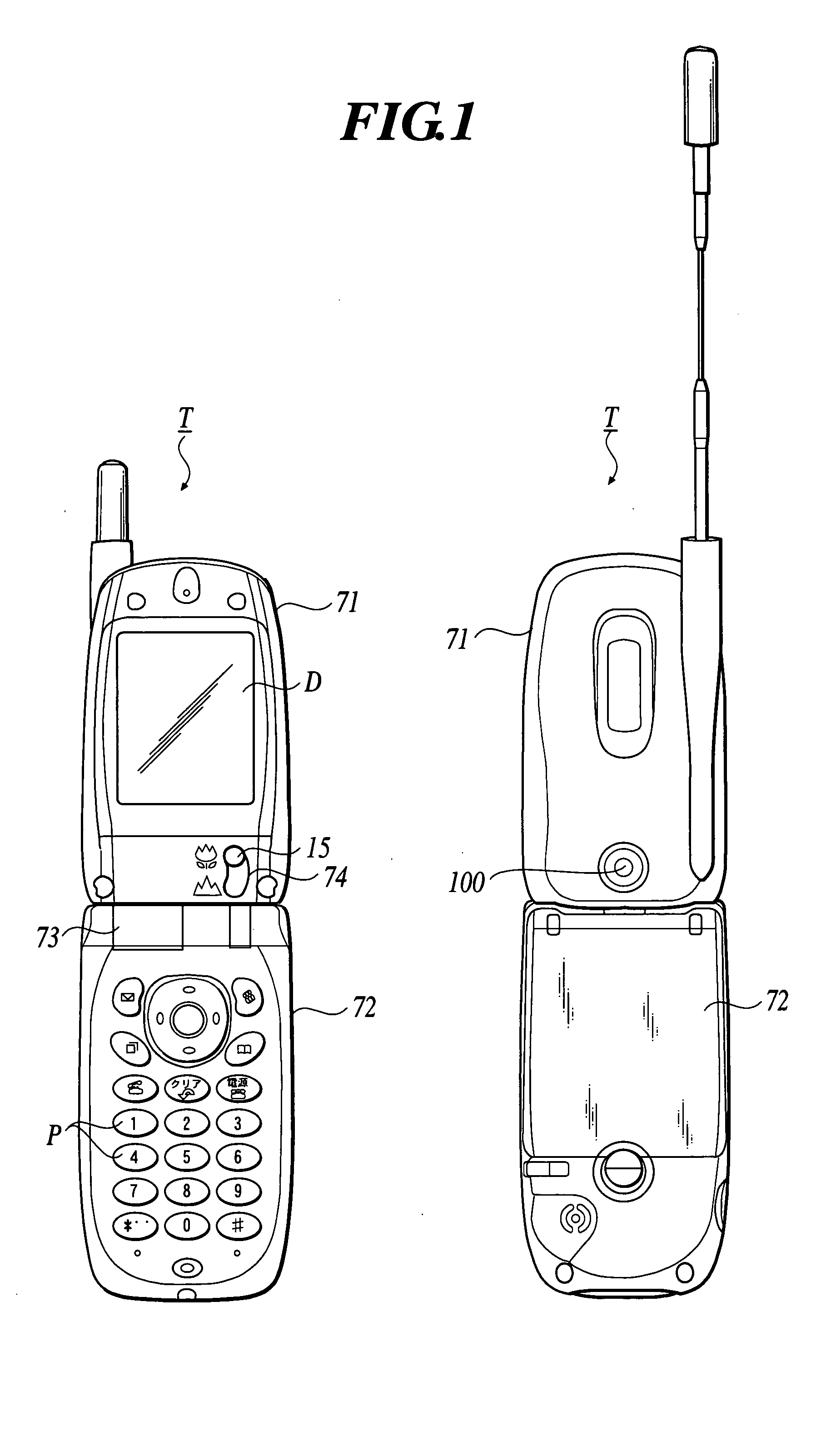
[0087]FIG. 1 is an illustration showing an appearance of a mobile phone T as an example of a portable terminal in which an image pickup device 100 of the present invention is incorporated.
[0088] In a mobile phone T, an upper package 71 as a case with a display screen D and a lower package 72 with manual operation buttons P are connected through a hinge 73. An image pickup device 100 is housed below the display screen D in the upper package 71, and arranged so as to take in light from the outer surface side of the upper package 71.
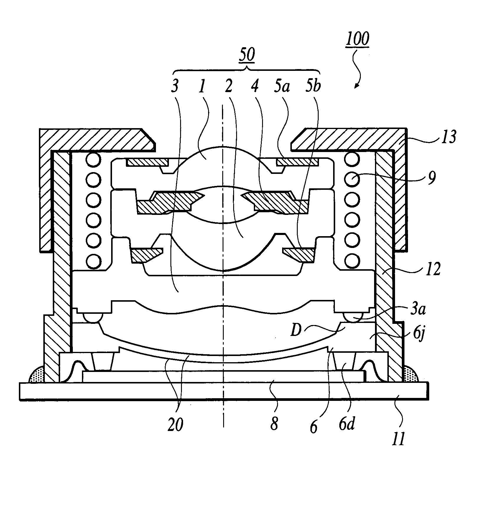
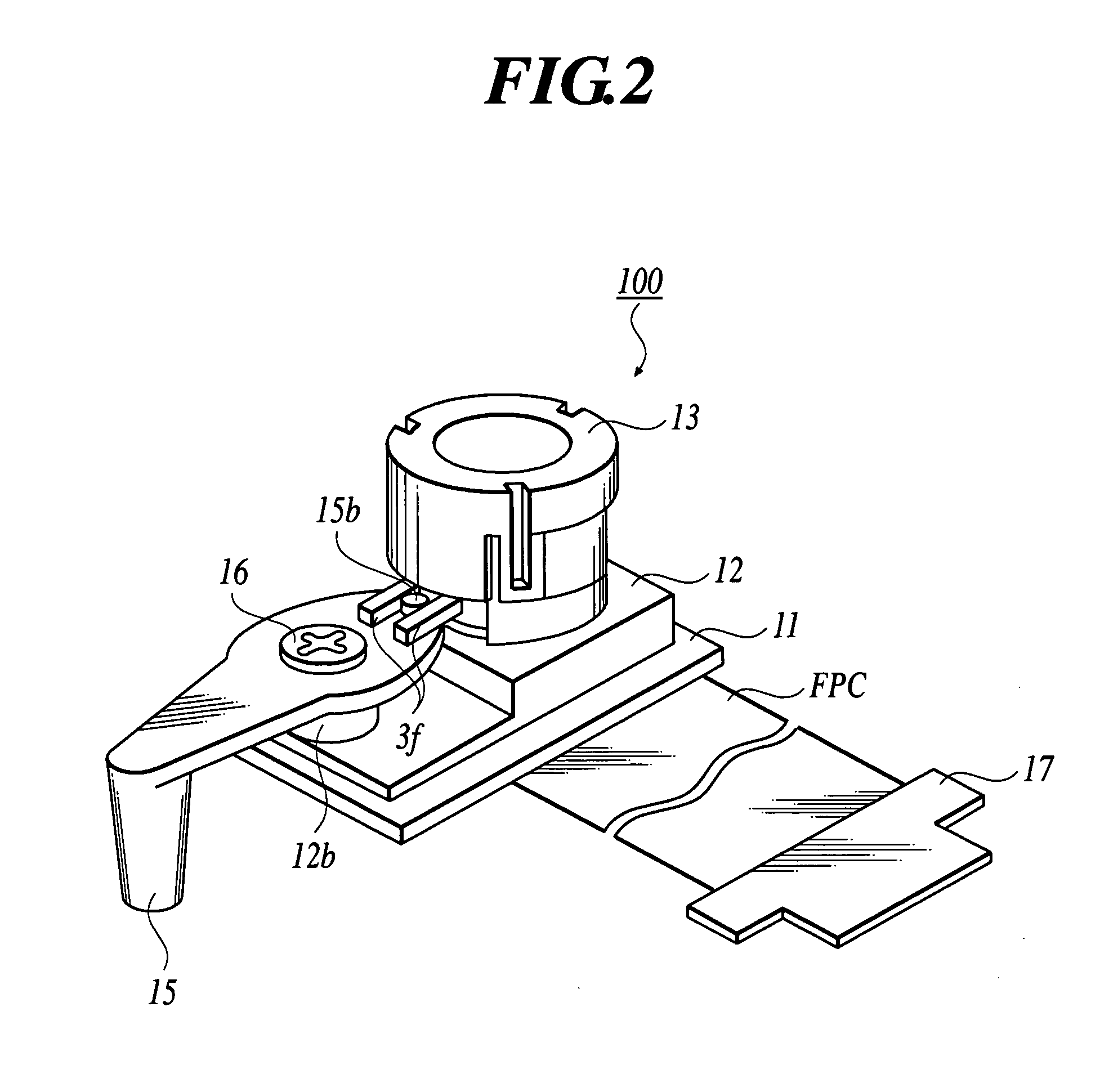
[0089] An arcuate opening 74 and a control member 15 are arranged below the display screen D of the upper package 71 so that the control member 15 is exposed from the opening 74. The focus distance is set for macro photography by moving the control member 15 upward in the figure in the opening 74.
[0090] The position...
PUM
 Abstract
Description
Claims
Application Information
 - Generate Ideas
- Intellectual Property
- Life Sciences
- Materials
- Tech Scout
- Unparalleled Data Quality
- Higher Quality Content
- 60% Fewer Hallucinations
Browse by: Latest US Patents, China's latest patents, Technical Efficacy Thesaurus, Application Domain, Technology Topic, Popular Technical Reports.
© 2025 PatSnap. All rights reserved.Legal|Privacy policy|Modern Slavery Act Transparency Statement|Sitemap|About US| Contact US: help@patsnap.com