Image forming apparatus

Inactive Publication Date: 2005-10-13
KONICA MINOLTA BUSINESS TECH INC
View PDF6 Cites 15 Cited by
  • Summary
  • Abstract
  • Description
  • Claims
  • Application Information

AI Technical Summary

Benefits of technology

[0025] With the above structures, the invention aims to provide image forming apparatuses having a fixing device with high productivity, durability performance, and the stability of image quality.
[0026] In above items (1) to (5), a pressure is applied at the entrance of a belt nip section, thereby tight contactness is improved over the entire area of the belt nip section, and thus, it is possible to provide an image forming apparatus having a fixing device with high productivity, durability performance, and the stability of image quality.

Problems solved by technology

However, with this type of roller fixing device, since the fixing rubber roller has a large thermal resistance and a large thermal capacity, warming up of the apparatus takes a long time, and the inner portion of the elastic layer rises in temperature, shortening the life of the fixing rubber roller.
Further, color images often have a large solid area, which is mostly in a color other than black, having a problem that a glaze mark, if there is, stands out.
However, in the above fixing devices, heat supply amount increases with speedup, the temperature difference between the surface of a rubber layer having a low thermal conductivity an

Method used


Image

  • Image forming apparatus
  • Image forming apparatus
  • Image forming apparatus

Examples


Example

[0033] In the following, preferred embodiments of the invention will be described. The description here does not limit the technical scope of the claims or the meanings of terms. The following affirmative description in the embodiments of the invention shows the best mode, and does not limit the meanings of the terms or the technical scope of the invention.

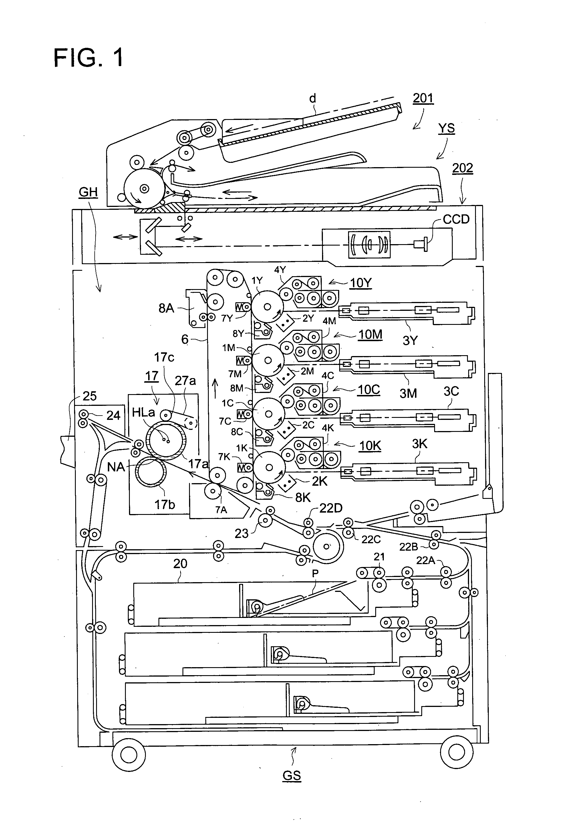
[0034] (1) An image forming apparatus provided with a fixing device having a heat belt in accordance with the invention will be described referring to FIG. 1.

[0035] In FIG. 1, an image forming apparatus GS includes an image forming basic device GH and an image reading device YS.

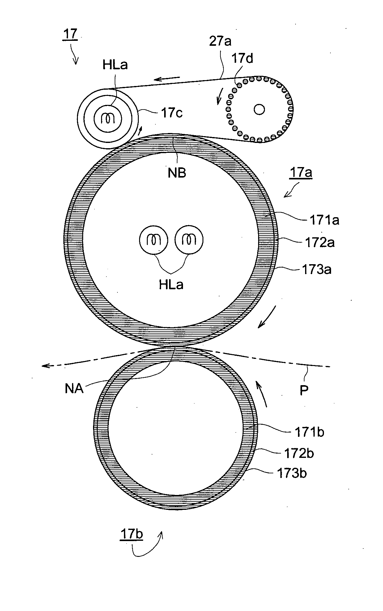
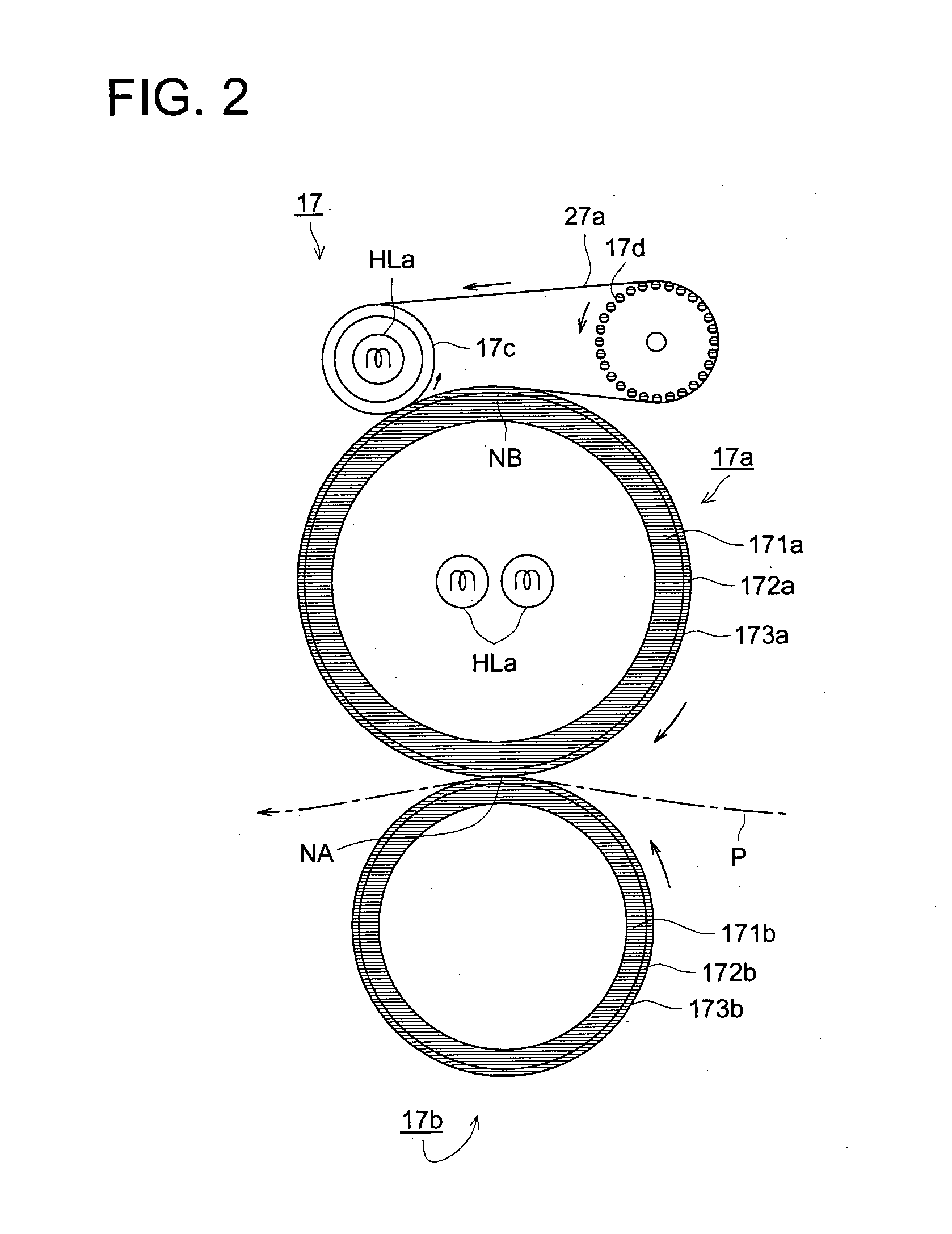
[0036] The image forming basic device GH is called a tandem-type color image forming device and includes a plurality of image forming sections 10Y, 10M, 10C, and 10K, an intermediate transferrer 6 in a belt shape, a sheet conveying unit, and a fixing device 17 having a separation assisting unit described later.

[0037] On the top of the image forming basi...


PUM


Abstract

There is provided an image forming apparatus having an image forming section for forming an unfixed image on a transfer medium and a fixing device for fixing the unfixed image by sandwiching and heating the transfer medium that holds the unfixed image, wherein, the fixing device includes a fixing roller that contacts with the unfixed image, a press roller that contacts with the fixing roller, a heat belt that contacts with the fixing roller and heats the fixing roller, a plurality of support rollers for supporting the heat belt in such a manner that the heat belt is wound around the support rollers, a heat source for heating the heat belt, and a press member for pressing the heat belt against the fixing roller in a portion of the contact area where the fixing roller and the heat belt contact with each other.

Description

FIELD OF THE INVENTION [0001] The present invention relates to an image forming apparatus including a fixing device used for image forming by copy machines, printers, facsimiles, and the like. BACKGROUND OF THE INVENTION [0002] As a fixing device used for an electrophotographic image forming apparatus such as a copy machine, a printer, or a facsimile, conventionally, a roller fixing device has been widely used which is by a heat roller fixing method. In the method, a fixing rubber roller, the fixing rubber roller having an elastic layer and maintained at a predetermined temperature, and a press rubber roller, the press rubber roller having an elastic layer and in press contact with the fixing rubber roller, heat a transfer medium on which an unfixed toner image has been formed, while sandwiching and conveying the transfer medium. [0003] However, with this type of roller fixing device, since the fixing rubber roller has a large thermal resistance and a large thermal capacity, warming...

Claims


Application Information

Patent Timeline
IPC IPC(8): G03G15/20
CPCG03G2215/2016G03G15/2017G03G2215/2019
Inventor FUMA, HIROSHI
Owner KONICA MINOLTA BUSINESS TECH INC
Why Eureka
Try Eureka