

Color filter and method for manufacturing the same, electro-optical device, and electronic apparatus
- Summary
- Abstract
- Description
- Claims
- Application Information
AI Technical Summary
Benefits of technology
Problems solved by technology
Method used
Image

Examples
first embodiment
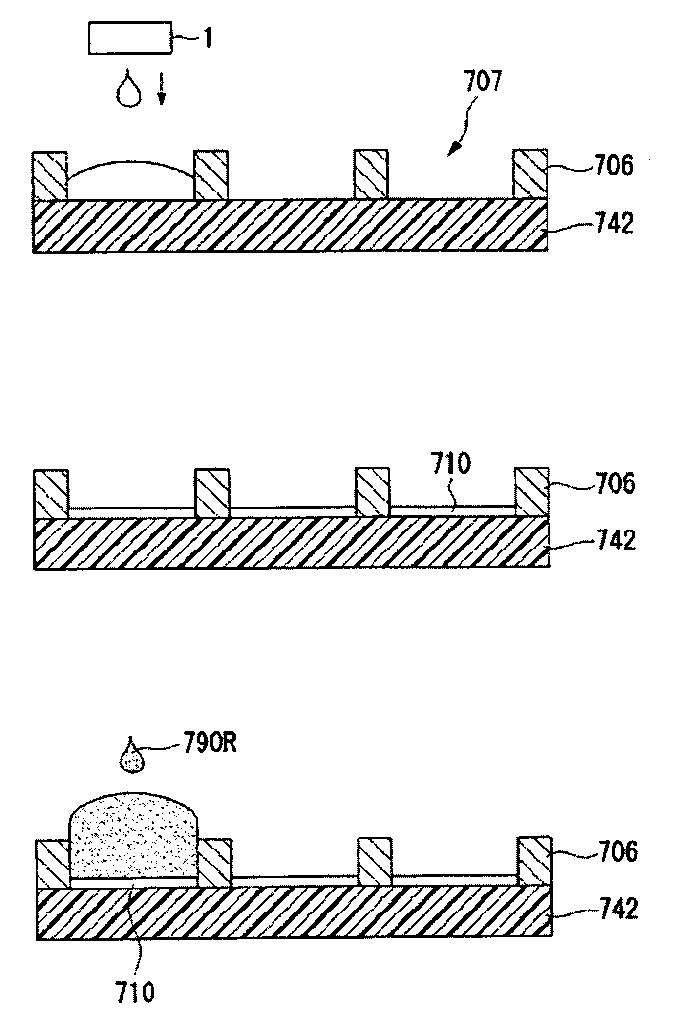
[0070] First, as shown in FIG. 6A, the partition wall 706 (black matrix) is formed against one surface of the transparent substrate 742. When forming this partition wall 706, a resin that does not transmit light (preferably, black-colored resin) is coated to have a given thickness (e.g., about 2 μm) by a method such as spin coating and is then patterned using a photolithography technique. Alternatively, an ink-jet process may be used
[0071] Further, when using the lithography method, an organic material is coated in accordance with the height of the partition wall by a given method such as spin coating, spray coating, roll coating, dye coating, dip coating, bar coating, or slit coating, and then a resist layer is coated thereon. Thereafter, in accordance with the configuration of the partition wall, masking is conducted so that the resist is exposed and developed and that the resist in accordance with the configuration of the partition wall remains. Finally, the partition wall mater...
second embodiment
[0084] Next, a second embodiment of the method for manufacturing the color filter of the invention will be described.
[0085] The first embodiment showed the case in which the color layers were formed after forming the lyophilic liquid layers 710 in all the plurality of filter element formation regions 707; while, the present embodiment will show a case in which the coloring ink is coated on the filter element formation region 707 each time the lyophilic liquid droplet is ejected to each filter element formation region 707.
[0086] In this embodiment, an aqueous dispersion of silica, in which fine particles of lyophilic silica (ST-K211 of Ishihara Sangyo Kaisha, Ltd.) are dispersed in alcohol, is ejected as the lyophilic liquid from the ink-jet head 1 to land inside the filter element formation region 707.
[0087] It is preferable that the fine particle of the silica has an average diameter of 1-500 nm, more preferably, 5-100 nm. Further, examples of the dispersing medium may be alcoho...
PUM
 Abstract
Description
Claims
Application Information