Apparatus for cleaning a distal scope end of a medical viewing scope

a technology for cleaning apparatus and medical viewing scope, which is applied in the field of medical equipment, can solve the problems of degrading the clarity of view, delay in laparoscopic procedure, inconvenience of laparoscope, etc., and achieves the effect of reducing the time for laparoscopic procedur

Inactive Publication Date: 2008-04-03
ETHICON ENDO SURGERY INC
View PDF55 Cites 340 Cited by
  • Summary
  • Abstract
  • Description
  • Claims
  • Application Information

AI Technical Summary

Benefits of technology

[0005]A first expression of a second embodiment of the invention is for apparatus for cleaning a distal scope end of a medical viewing scope. The apparatus includes a motor-driven rotatable cannula having an open proximal cannula end and having a transparent and closed distal cannula end. The scope is insertable into the proximal cannula end with the distal scope end disposed proximate and spaced apart from the distal cannula end. Rotation of the cannula helps to expel any material that has accumulated on the distal cannula end when the cannula is inserted into a patient.
[0007]A first expression of a fourth embodiment of the invention is for apparatus for cleaning a distal scope end of a medical viewing scope. The apparatus includes an annular sheath having open proximal and distal sheath ends and a rotatably-driven transparent shield rotatably attachable to the sheath proximate the distal sheath end to seal the distal sheath end. The scope is insertable into the proximal sheath end with the distal scope end disposed proximate and spaced apart from the shield. Rotation of the shield helps to expel any material that has accumulated on the shield when the sheath and the attached shield are inserted into a patient.
[0009]Several benefits and advantages are obtained from one or more of the expressions of embodiments of the invention which provide cleaning of a distal scope end of a medical viewing scope while the scope remains inserted in a patient. In one example, not removing the scope for cleaning and not reinserting the cleaned scope reduces the time for a laparoscopic procedure. In the same or a different example, not removing the scope for cleaning and not reinserting the cleaned scope keeps the inserted scope aligned with the patient tissue of interest during cleaning so that the physician does not have to take additional time to maneuver the scope to reacquire the patient tissue of interest.

Problems solved by technology

Bodily fluid dispersion and floating debris have a tendency to accumulate on the scope lens of the inserted laparoscope degrading the clarity of the view.
The removal of the laparoscope is inconvenient and causes delays in the laparoscopic procedure.
In one example, not removing the scope for cleaning and not reinserting the cleaned scope reduces the time for a laparoscopic procedure.

Method used


Image

  • Apparatus for cleaning a distal scope end of a medical viewing scope
  • Apparatus for cleaning a distal scope end of a medical viewing scope
  • Apparatus for cleaning a distal scope end of a medical viewing scope

Examples


first embodiment

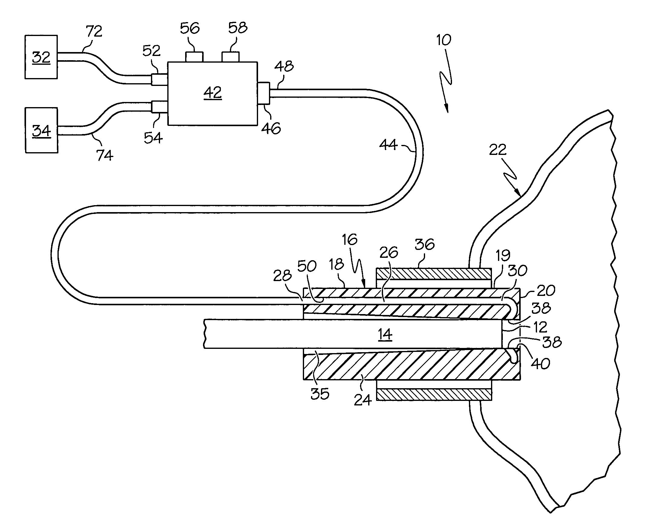
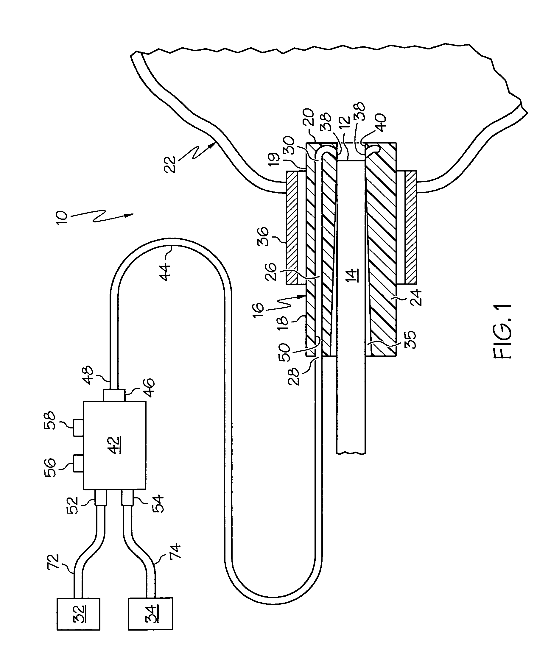
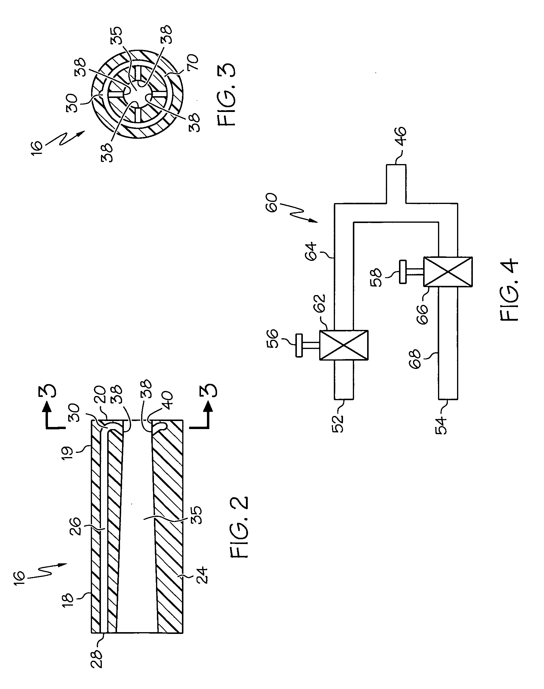
[0027]the invention is shown in FIGS. 1-4. A first expression of the embodiment of FIGS. 1-4 is for apparatus 10 for cleaning a distal scope end 12 of a medical viewing scope 14. The apparatus 10 includes an annular sheath 16 having open proximal and distal sheath end portions 18 and 19. The sheath 16 is surroundingly attachable to the scope 14 and is insertable into a patient 22. The sheath 16 includes a tubular wall 24 having inside and outside diameters and containing a lumen 26 between the inside and outside diameters. The lumen 26 has proximal and distal lumen ends 28 and 30. The proximal lumen end 28 is fluidly connectable to at least one of an irrigation fluid source 32 and a vacuum source 34. The distal scope end 12 is in fluid communication with the distal lumen end 30 of the attached sheath 16. It is noted that the inside diameter of the tubular wall 24 is the diameter of a bore 35 into which the scope 14 is insertable. In an alternate first expression, a scope assembly in...

second embodiment

[0038]the invention is shown in FIGS. 5-6. A first expression of the embodiment of FIGS. 5-6 is for apparatus 110 for cleaning a distal scope end 112 of a medical viewing scope 114. The apparatus 110 includes a motor-driven rotatable cannula 116 having an open proximal cannula end 118 and having a transparent and closed distal cannula end 120. The scope 114 is insertable into the proximal cannula end 118 with the distal scope end 112 disposed proximate and spaced apart from the distal cannula end 120. Rotation of the cannula 116 helps to expel any material that has accumulated on the distal cannula end 120 when the cannula 116 is inserted into a patient. It is noted that the cannula 116 surrounds a cannula bore 121 into which the scope 114 is insertable and that the closed distal cannula end 120 closes the cannula bore 121. In an alternate first expression, a scope assembly includes the apparatus 110 and the scope 114, wherein the scope 114 is inserted into the cannula 116.

[0039]In ...

third embodiment

[0040]the invention is shown in FIGS. 7-9. A first expression of the embodiment of FIGS. 7-9 is for apparatus 210 for cleaning a distal scope end 212 of a medical viewing scope 214. The apparatus 210 includes an annular sheath 216 and a lens 217. The sheath 216 has open proximal and distal sheath ends 218 and 220. The lens 217 is disposed in and attached to the sheath 216 and closes off the sheath 216 proximate the distal sheath end 220. The lens 217 has a distal surface 221. The scope 214 is insertable into the proximal sheath end 218 with the distal scope end 212 disposed proximate the lens 217. The sheath 216 is insertable into a patient 222. The sheath 216 includes a tubular wall 224 having inside and outside diameters and containing a lumen 226 between the inside and outside diameters. The lumen 226 has proximal and distal lumen ends 228 and 230. The proximal lumen end 228 is fluidly connectable to at least one of an irrigation fluid source 232 and a vacuum source 234. The dist...


PUM


Abstract

A first apparatus for cleaning a distal end of a medical scope includes an annular sheath surroundingly attachable to the scope wherein the distal scope end is in fluid communication with the distal end of a lumen of the attached sheath with the proximal lumen end fluidly connectable to an irrigation fluid source and / or vacuum source. A second apparatus includes a motor-driven rotatable cannula having a closed distal end. A third apparatus includes an annular sheath and a lens which closes off the sheath, wherein the scope is insertable into the sheath, and wherein the lens is exposed to a distal lumen end of a lumen of the attached sheath. A fourth apparatus includes an annular sheath and a transparent shield rotatable attachable to the sheath to seal the distal sheath end. A fifth apparatus includes a sleeve attachable to and slidable along a scope.

Description

FIELD OF THE INVENTION[0001]The present invention is related generally to medical equipment, and more particularly to apparatus for cleaning a distal scope end of a medical viewing scope.BACKGROUND OF THE INVENTION[0002]During some conventional laparoscopic procedures, first and second trocars are used to create two openings in the patient's abdomen. A rigid laparoscope is inserted through the first trocar to visualize patient tissue. A treating medical instrument is inserted through the second trocar to treat the patient tissue being visualized with the laparoscope. Bodily fluid dispersion and floating debris have a tendency to accumulate on the scope lens of the inserted laparoscope degrading the clarity of the view. Thus, at times during the laparoscopic procedure the laparoscope must be withdrawn from the first trocar and the scope lens wiped to remove the accumulated material which caused the blurred viewing. The removal of the laparoscope is inconvenient and causes delays in t...

Claims


Application Information

Patent Timeline
Patent Type & Authority Applications(United States)
IPC IPC(8): A61B1/12
CPCA61B1/00135A61B1/126A61B1/3132A61B1/127
Inventor WEISENBURGH, WILLIAM B.GILL, ROBERT P.HESS, CHRISTOPHER J.CUMMINGS, JOHN F.
Owner ETHICON ENDO SURGERY INC
Why Eureka
Try Eureka