
Mobile Power Supply

Inactive Publication Date: 2008-04-10
POWERCART SYST
View PDF16 Cites 16 Cited by
  • Summary
  • Abstract
  • Description
  • Claims
  • Application Information

AI Technical Summary

Benefits of technology

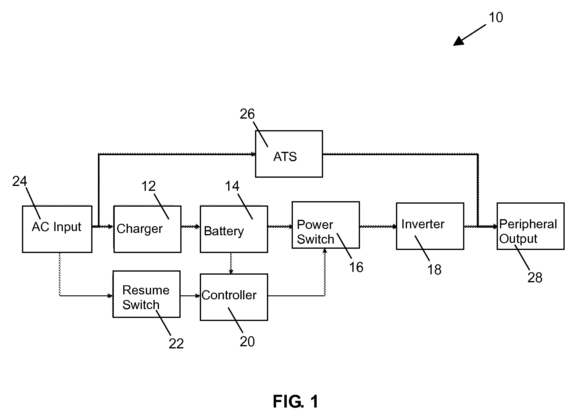
[0008]According to another aspect, there is provided a mobile power supply. The power supply includes a charger connectable to an AC power supply for charging the battery, a power switch connectable to the battery for turning power from the battery on and off, an inverter connectable to the battery for converting direct current from the battery to alternating current for supplying power to a load, a controller for controlling the power switch for turning off all power from the battery when the battery reaches a predetermined power off state of charge or voltage, and a resume switch for resuming power to the controller in response to receipt of power from the AC power supply, thereby causing the controller to resume monitoring of the state of charge and voltage of the battery. When the battery reaches a predetermined power off state of charge or voltage, the controller switches off the power switch and turns off all power from the battery including power to itself. The controller is turned back on by the resume switch, in response to receipt of power from the AC power supply. When the battery is recharged and reaches a predetermined restart state of charge and voltage, the controller switches on the power switch.
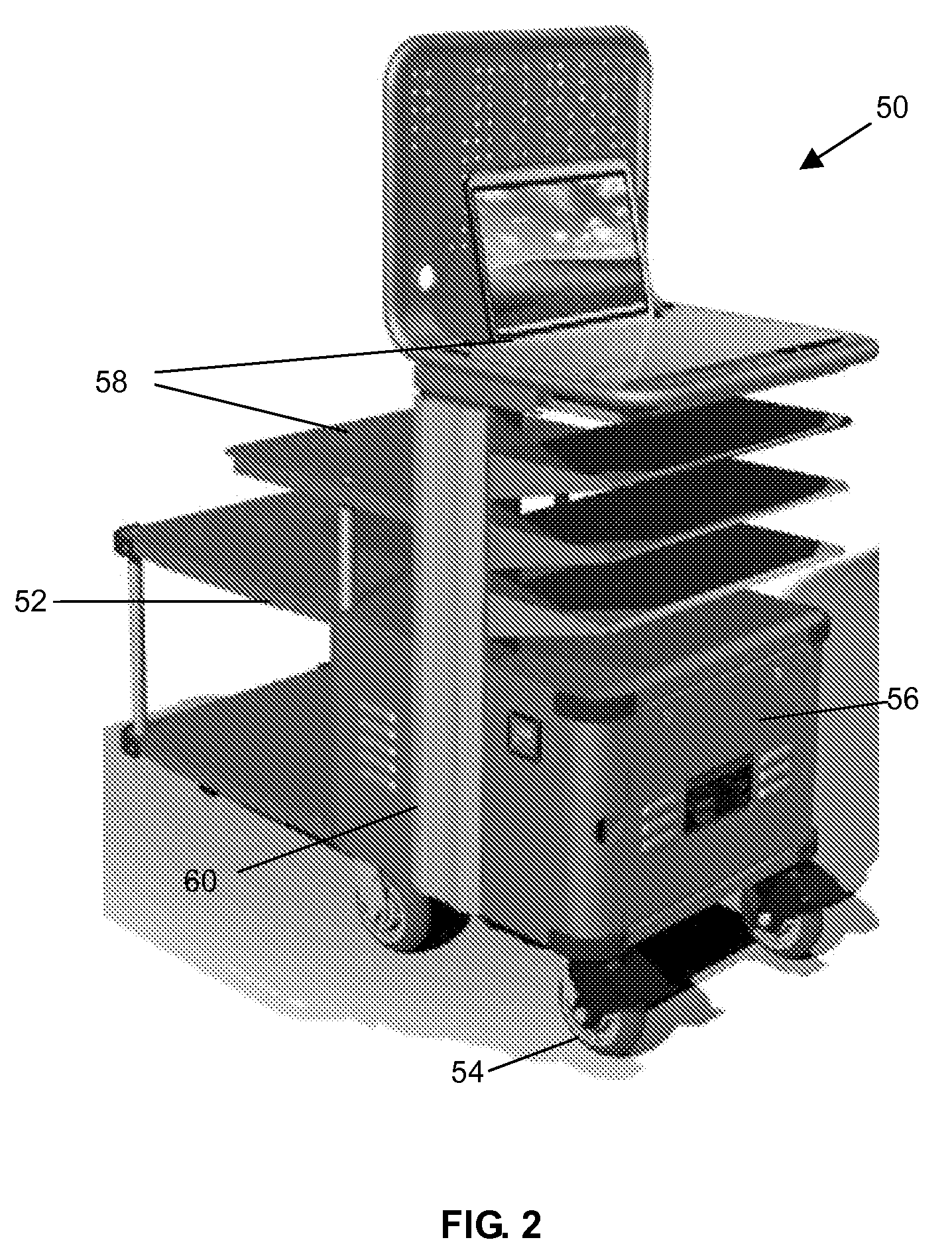
[0009]According to yet another aspect, there is provided a mobile cart for use with a battery. The mobile cart includes a body, a plurality of wheels connected to and supporting the

Problems solved by technology

These batteries have a limited lifetime, which is nonlinearly related to the chemical composition, application, environmental factors, and use / maintenance.
Performance of batteries such as lead-acid batteries degrades quickly with deep discharge of the battery and cycling to deep discharge of the battery, thereby further reducing the expected lifetime of the battery.
Thus, the battery continues to discharge after reaching the predetermined state of charge which leads to deep discharge of the battery, resulting in battery degradation and reduced battery lifetime.

Method used


Image

  • Mobile Power Supply
  • Mobile Power Supply
  • Mobile Power Supply

Examples


Embodiment Construction

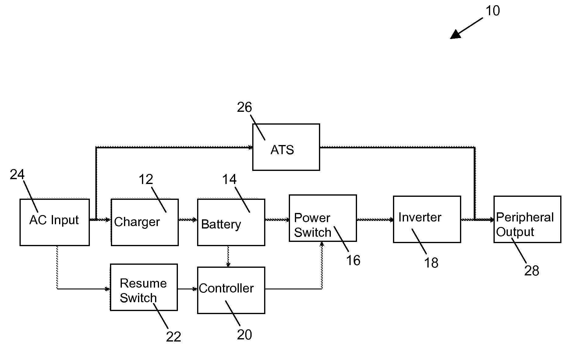
[0014]Reference is first made to FIG. 1 which shows a schematic representation of a mobile power supply including a system for controlling battery usage according to one embodiment of the present invention. The mobile power supply in the schematic illustration of FIG. 1 is indicated generally by the numeral 10. The mobile power supply 10 includes a charger 12 connectable to an AC power supply for charging the battery 14. A power switch 16 is connectable to the battery 14 for turning power from the battery 14 on and off and an inverter 18 is connectable to the battery 14 for converting direct current from the battery 14 to alternating current for supplying power to a load. A controller 20 is provided for controlling the power switch 16 for turning off all power from the battery 14 when the battery 14 reaches a predetermined power off state of charge or low voltage condition. A resume switch 22 is provided for resuming power to the controller 20 in response to receipt of power from th...


PUM


Abstract

A system for controlling battery usage in a mobile power supply includes a controller for monitoring a state of charge of the battery and the voltage and switching off all power from the battery when the battery reaches a predetermined power off state of charge or a low voltage condition. A switch provides power to the controller in response to receipt of power from an other source, thereby causing the controller to resume monitoring of the state of charge of the battery. When the battery reaches a predetermined power off state of charge, the controller switches off power from the battery. The switch turns the controller back on in response to receipt of power from the other source. When the battery is recharged to a predetermined restart state of charge and when the voltage reaches a restart voltage, power from the battery is switched back on.

Description

TECHNICAL FIELD[0001]The present invention relates to mobile power supplies for use with, for example, wheeled carts such as patient point of care carts in health care facilities, for providing portable power for various applications.BACKGROUND OF THE INVENTION[0002]Wheeled carts including mobile power supplies are increasingly being used in various applications including retail applications for mobile, temporary or portable checkout locations, warehousing applications for barcode reading, barcode labeling, radio frequency identification (RFID) tag labeling and reading, and inventory tracking, and health care applications for carrying and powering patient care equipment such as monitors, pumps, ventilators or computers for tracking patient related data. With this increase in popularity, there is also an increase in the demand for improvements in wheeled carts including mobile power supplies.[0003]Referring in particular to the health care environment, an uninterrupted supply of powe...

Claims


Application Information

Patent Timeline
IPC IPC(8): H02J7/00
CPCG06F1/263H02J7/02H02J7/0031G06F1/30H02J7/00306H02J5/00
Inventor CUTRONA, ANTHONY J.
Owner POWERCART SYST
Learn More